11
4.0 INSTALLATION
4.4.3 Liquid Line Selection
The purpose of the liquid line is to transport warm
sub-cooled liquid refrigerant between the outdoor
unit to the indoor unit. It is important not to allow the
refrigerant to ash into superheated vapor prior to en-
tering the expansion device of the indoor coil or outdoor
unit. Flashing of refrigerant can occur for the following
reasons:
• Low refrigerant charge.
• Improperly selected liquid line size.
• Absorption of heat prior to expansion device.
• Excessive vertical separation between the outdoor
unit and indoor coil.
• Restricted liquid linear lter drier.
• Kinked liquid line.
The total pressure drop allowed for the liquid line is 50
PSI [345 kPa]. The procedure for selecting the proper
liquid line is as follows:
• Measure the total amount of vertical separation be-
tween the outdoor unit and indoor coil.
• Measure the total indoor length of liquid line re-
quired.
• Add all of the equivalent lengths associated with any
ttings or accessories using Table 1.
• Add the linear length to the total tting equivalent
length. This will equal your total equivalent line
length.
• Reference Table 2 to verify the calculated equivalent
length is acceptable with the required vertical sepa-
ration and diameter of liquid line.
Example: A 3-ton unit is installed 25’ below the indoor
unit, requires 75’ of 1/2” diameter liquid line, 3/4” suction
line, 4 90° LR elbows, and a lter drier.
• Fitting Equivalent Length (ft.) = (4 × .9’) + 6’ = 9.6’
• Total Equivalent Length (ft.) = 75’ + 9.6’ = 84.6’
This application is acceptable because the 25’
vertical rise is less than the maximum rise of 50’ for
this application. This application is also considered to
have a lone line set since 75’ exceeds the limit of 0 feet.
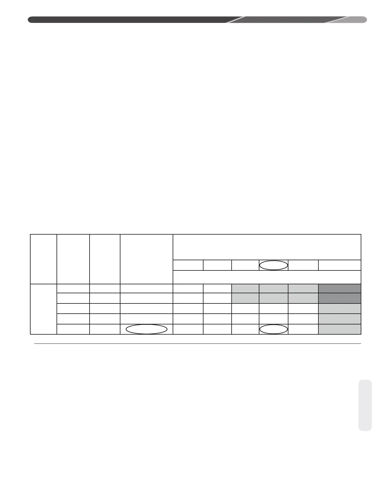
Unit
Size
Allowable
Liquid
Line
Size
Allowable
Suction
Line
Size
Use Long Line
Guidelines for
Linear Line
Lengths Greater
Than Shown
Below
(Feet)
Outdoor Unit ABOVE or BELOW Indoor Unit
Equivalent Length (Feet)
<25 26-50 51-75 76-100 101-125 126-150
Maximum Vertical Separation (Outdoor Unit Below Indoor Unit)* / Capacity Multiplier
3 Ton
5/16” 5/8” 20 25 / 0.99 50 / 0.97 50 / 0.95 50 / 0.93 36 / 0.91 NR
3/8” 5/8” 15 25 / 0.99 50 / 0.97 50 / 0.95 50 / 0.93 50 / 0.91 NR
5/16” 3/4” 20 25 / 1.00 50 / 0.99 50 / 0.99 50 / 0.98 36 / 0.97 18 / 0.96
3/8” 3/4” 15 25 / 1.00 50 / 0.99 50 / 0.99 50 / 0.98 50 / 0.97 50 / 0.96
1/2” 3/4” 0 25 / 1.00 50 / 0.99 50 / 0.99 50 / 0.98 50 / 0.97 50 / 0.96
(Excerpt from Table 2A)
4.4.4 Suction Line Selection
The purpose of the suction line is to return super-
heated vapor to the condensing unit from the
indoor coil. Proper suction line sizing is important be-
cause it plays an important role in returning oil to the
compressor to prevent potential damage to the bearings,
valves, and scroll sets. Also, an improperly sized suction
line can dramatically reduce capacity and performance
of the system. The procedure for selecting the proper
suction line is as follows:
• Determine the total linear length of suction line
required.
• Add all of the equivalent lengths associated with any
ttings or accessories using Table 1.
• Add the linear length and total tting equivalent
length. This will equal your total equivalent line
length.
• Reference Table 2 to verify that the calculated equiv-
alent length falls within the compatibility region of the
chart.
• Verify capacity loss is acceptable for the application.
Tubing
 Loading...