Guardian PowerVent Training Manual SVC900; Rev 1
Page 12
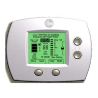
Turn temperature dial to
temperature selection.
Initiates a “call for heat”.
120V power is passed from
the red #3 wire – thru the
control – to the yellow #5
wire and to the blower
motor. This is the only
source of AC power for the
blower motor.
The white triangle next to
WARM is the 120-degree
setting.
Temperature is sensed
electronically by the
Thermistor in the sensing
bulb. It is the two white
wires at the RED Molex
connector.
(See Fig 3 on page 10.)
(1st Safety)
Control checks for OPEN
vacuum switch.
You will have 120V at the
blue #8-vacuum switch
wire.
Note: The over-temp switch
in the blower is wired in
series. If the vent temp
exceeds 180
0
F, then the
over-temp switch will
activate. LED will flash 3/3.
In normal operation, the
switch is OPEN at beginning
of call for heat. If no blower
motor, then check:
120V power at the #5 yellow
wire
Vacuum switch tubing
Vacuum switch
Vent over-temperature
switch is not activated
If vacuum switch has failed
in the closed position, the
control attempts to open the
switch by cycling (turning
off blower, then on) the
blower motor. After 5 cycles
(attempts), the control will
lockout. LED code is 3/1.

 Loading...