Guardian PowerVent Training Manual SVC900; Rev 1
Page 17
TIMING AND SETTINGS
Unless otherwise noted, all nominal functional timings are to be accurate to ± 1 second or 5%,
whichever is greater, over the specified operating temperature and voltage ranges
Timing/ Setting Nominal
Temperature differentials (factory pre-set) 15
Temperature set point range 95
0
- 158
0
Flame Establishing Period 2 Seconds
Flame Failure Response Time 2 Seconds
Recycle Time 15 Seconds
Lockout Time 285 + pre-purge time in Seconds
Vacuum switch short cycle 9 Seconds
Vacuum switch long cycle 12 Seconds
Pre-purge time (factory pre-set) 15Seconds
Inter-purge Time 30 Seconds
Post-purge Time (factory pre-set) 30 Seconds
Ignition Activation Period 75 Seconds
Trial for Ignition Period 75 Seconds
Valve Sequence Period 225 Seconds
Automatic Restart Time 60 minutes
Number of ignition trials 3 times / trails
Table 3 – Timings and Settings
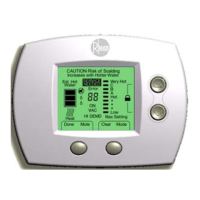
DIAGNOSTIC FLASH CODES
Another new feature of the Guardian PowerVent is the LED diagnostics system built into the
control module. When the unit faults, the LED will flash a
certain number of times. A flashing green LED diagnostic code
indicates that a sequence of events has forced a lockout
condition and is in a lockout state. Number of flashes indicates
the type of failure. The flash code or number of flashes will
occur followed by a pause before it repeats. Any power
interruption of more than 2 seconds – with the reapplication of
power, will re-set the controls. If a fault condition existed prior
to the reset, the fault condition will clear with the exception of
the FV sensor codes. If the fault condition still exists after the
application of power, the control will indicate the appropriate
fault.
Figure 4 – Flash Code LED
A green LED is provided to indicate system status.
When a fault occurs within the water heater, the control will output a code using an LED.

 Loading...