Guardian PowerVent Training Manual SVC900; Rev 1
Page 11
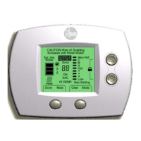
SEQUENCE OF OPERATIONS
All voltage inputs are 120V. Neither a surge protector nor GFI circuit is recommended or
required. All electrical connectors are Molex and fit one way. The word ‘control’ in this
sequence will normally refer to the electronic control module on the gas valve. The control
constantly monitors the water temperature via the thermistor so that the water temperature is
within the user-selected temperature range. Control monitors the inputs for any fault conditions
and presence of flammable vapors. If “Call for Heat” has not initiated for more then 6 hours, the
control will automatically decrease the differential by 5°F. If the temperature is still not less than
the set temperature minus differential, the control continues in Stand-by mode.
Tank is cold and full of
water.
Gas supply is connected.
Gas valve is set to ON
position.
Unit is plugged into a 3-
prong plug. Unit is polarity
sensitive.
Fill tank.
Connect gas.
Turn valve ON.
Must be plugged
into a 3-prong
wall socket. Socket must be
wired polarity correct. Black
wire to brass screw; white
wire to silver screw.
Turn temperature dial down
to LOWEST position.
Turn rocker switch to ON
position.
Rocker switch controls all
power inputs to blower
motor, gas valve, and control
module in gas valve. You
will always have 120V at the
red #3 wire.
At power ON and a demand
for heat, the control performs
a self-test diagnostic routine.
If the self-check fails, the
control locks out with a solid
ON LED light.

 Loading...