Guardian PowerVent Training Manual SVC900; Rev 1
Page 2
Table 6 – Venting the Guardian PowerVent................................................................................. 27
Table 7 – Guardian PowerVent Troubleshooting Table............................................................... 30
Index of Figures
Figure 1 – Components of Guardian PowerVent Burner Assembly............................................... 7
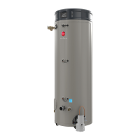
Figure 2 – Components of a Guardian PowerVent Water Heater .................................................. 8
Figure 3 – Wiring Harness Connection Diagram ......................................................................... 10
Figure 4 – Flash Code LED .......................................................................................................... 17
Figure 5 – Blower Motor .............................................................................................................. 21
Figure 6 – Vacuum Switch ........................................................................................................... 22
Figure 7 – Thermistor and ECO Check ........................................................................................ 23
Figure 8 – FV Wiper Gas Control................................................................................................. 23
Figure 9 – Vent Over Temperature Safety Switch........................................................................ 24
Figure 10 – Ignitor Assembly ....................................................................................................... 25
Figure 11 – Gas Valve Connections ............................................................................................. 25
Figure 12 – Flammable Vapor Sensor Check............................................................................... 26
Figure 13 – Connection Diagram.................................................................................................. 26
Figure 14 – Invensys Reset Procedure.......................................................................................... 44
Figure 15 – White Rodgers Control Gas Valve ............................................................................ 45
Figure 16 – White Rodgers Connection Diagram......................................................................... 51
Before inspecting, diagnosing, repairing or operating any water heater, be sure
to examine all of the safety and warning labels on the tank. Follow the
instruction on these warning labels. Read and understand the Use and Care
Manual that was shipped with the water heater. Failure to do so can result in
unsafe operation of the water heater resulting in property damage, bodily injury,
or death. Should you have any problems reading or following the instructions in the Use and
Care Manual, seek the help of a licensed and qualified professional.
NOTICE: This unit is equipped with a Flammable Vapor Sensor. Venting installation of
this flammable vapor ignition resistant water heater involves the use of PVC glue. PVC
glue emits flammable vapors. Do not apply power until enough time has passed to allow the
vapors from the PVC primer and cement to dissipate. Installation in locations with ambient
air over 100 degrees F may lock out the controls.
Copyright 2008, Rheem Manufacturing Company, Water Heater Division.

 Loading...