TM090 12-26 Series II CFGWH Service Instructions
REV AB – Issued February 2019
This document is stored and maintained electronically by Rheem Technical Support. All printed copies are deemed “uncontrolled”
Tests 12-15A
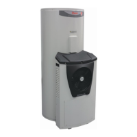
Test 13 – Solenoid valve 2
Conduct test with water flowing
When ignition sequence commences, normal
voltage should read DC 9-15 Volts between 11
Black and 9 Orange, until flame is detected.
(Note: Duration is approximately 3 seconds)
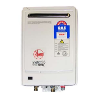
Conduct test with water flowing
Measure the voltage with connector I
plugged into PCB between 11 Black and 8
Red
Measure the resistance with connector I
unplugged from the PCB between 11 Black
and 8 Red
Components will be “Live” when conducting tests, exercise caution.
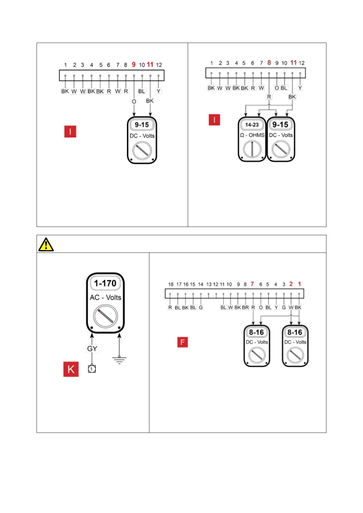
Test 15 A – Water inlet valve
Conduct test with water flowing
Measure the voltage with connector
K plugged into PCB. reading AC1 -
170V. between 1 Grey and Earth
Conduct test with water flowing
Measure the voltage with connector F plugged into PCB.
reading DC 8-16 Volts. Between 1 Black and 2 White and
between 1 Black and 7 Red.
 Loading...