COMFORT CONTROL
2
SYSTEM™ CONTROL WIRING
Thermostat Connector (E2)
• R – 24VAC from the indoor unit 24VAC transformer (40 VA minimum)
• C – 24VAC Common from the indoor unit 24VAC transformer
• 1-Data: System Communications Line 1
• 2-Data: System Communications Line 2
Low Volt Fuse
• If required replace with 3 A automotive ATC style blade fuse
Low Pressure Control (LPC Input)
• Low-pressure control is factory installed
• Low pressure control is an automatic resetting device
High Pressure Control (HPC Input)
• High-pressure control is factory installed
• High pressure control is an automatic resetting device
Ambient Temperature Sensor (included with all applications)
• Included with all applications
TEST and SW2 Buttons
• TEST and SW2 buttons used to enter Test and Fault Recall Mode
Memory Card
• The memory card stores all unit information.
• The unit information is called shared data.
• The shared data is all the information needed for proper unit operation.
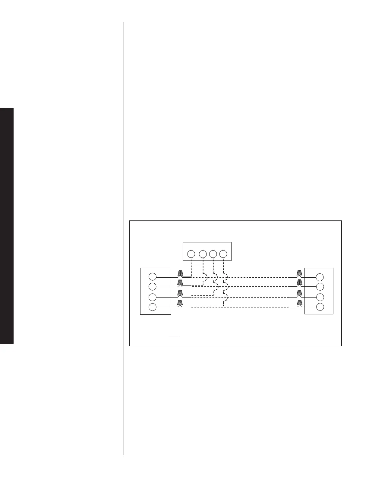
FIGURE 5
TYPICAL COMFORT CONTROL
2
SYSTEM™ WIRING DIAGRAM
Indoor Unit
1
2
C
R
WIRING INFORMATION
Line Voltage
–Field Installed - - - - - -
–Factory Standard
1
2
R
C
1
2
R
C
Communicating Thermostat
Outdoor Unit
18

 Loading...