CONVENTIONAL THERMOSTAT WIRING
12.7 Conventional 24VAC Thermostat Control Wiring
The (-)PRL series of heat pumps allow the installer to use conventional 24VAC con-
trol wiring and a conventional thermostat for proper unit operation.
IIMMPPOORRTTAANNTT::
The preferred method of unit installation and operation is by the
Comfort Control
2
System™, which allows access to the fault history of the system.
This diagnostic information is not available when the (-)PRL unit is using a conven-
tional thermostat. Reference section 12.2 Comfort Control
2
System™ Control
Wiring.
Thermostat control wiring requires a minimum of six (6) wires for proper unit opera-
tion:
R – 24VAC
C – 24VAC common
Y1 – First stage operation
Y2 – Second stage operation
B – Heat pump operation
D – Defrost
Optional wiring:
L – ICC fault information
L Terminal Output
• Flash 1 – Compressor running extremely long run cycle or low pressure
• Flash 2 – High pressure control trip
• Flash 3 – Unit short cycling
• Flash 4 – Locked rotor
• Flash 5 – Compressor will not run, open circuit
• Flash 6 – Open start circuit
• Flash 7 – Open run circuit
• Flash 8 – Control mis-operation
• Flash 9 – Low control voltage
When the L terminal from the outdoor unit is connected to a conventional thermo-
stat that is L terminal compatible, the thermostat display will flash the above codes.
If the low voltage control wiring is run in conduit with the power supply, Class I insu-
lation is required. Class II insulation is required if run separate. Low voltage wiring
may be run through the insulated bushing provided in the 7/8 hole in the base
panel, up to and attached to the pigtails from the bottom of the control box. Conduit
can be run to the base panel if desired by removing the insulated bushing.
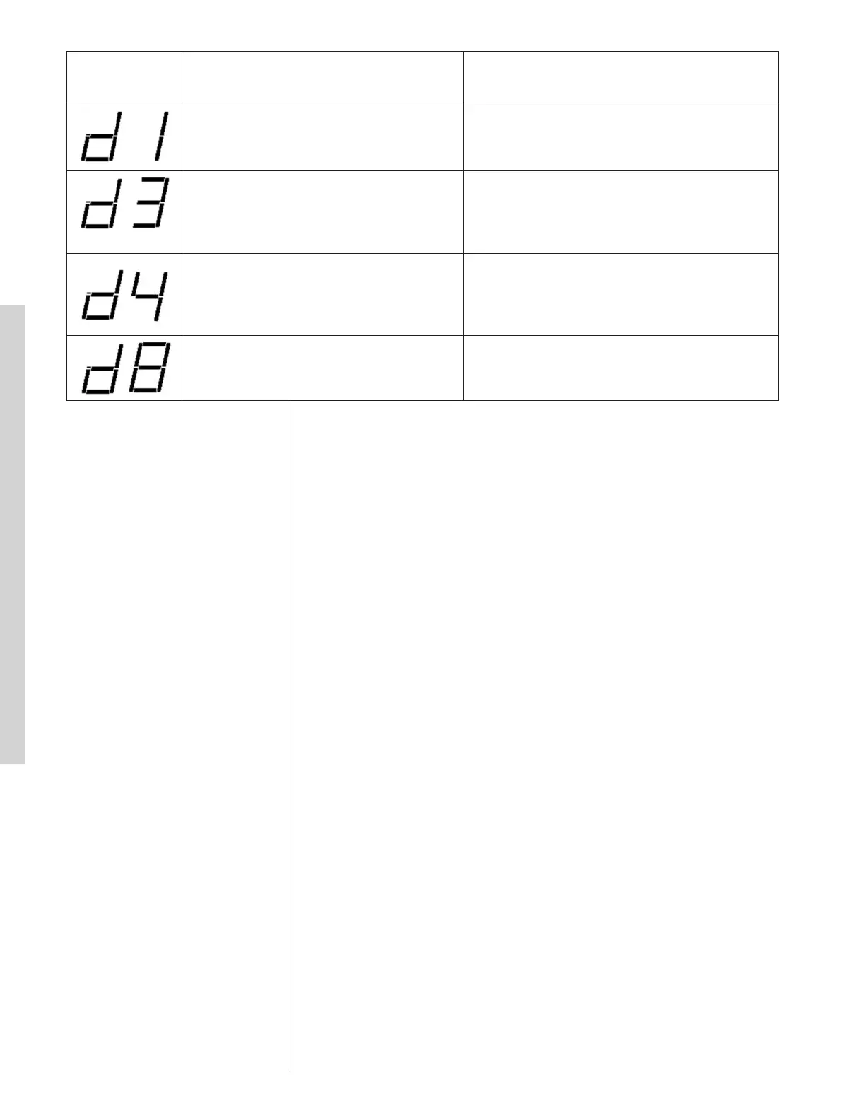
Dual 7-Segment
LEDs Display
Code
Diagnostic Description
Status/Possible Cause – Troubleshooting
Information
d
1 – No Shared Data • Replace memory card with correct system
information.
11
d1 – No Shared Data
ELECTRONICS GROUP TO
DESCRIBE
d3 – Airflow CFM Mismatch
The indoor air mover (air handler/furnace)
cannot supply the required airflow for
proper system operation
• Misapplied/wrong indoor air mover – replace
with properly sized air handler/furnace.
P – Protector Trip
A command for compressor operation is
present but no current is measured to the
compressor
• Motor protector open
• Line voltage disconnected
01 – Long Run Time (Compressor)
The compressor has continuously run for
more than 18 hours in the cooling mode.
• Low refrigerant charge
• Air ducts have substantial leakage
• Dirty indoor air filter
• Dirty outdoor coil
02 – High Pressure Control Open
The ICC detects the HPC is open.
Reference ICC codes:
• 21
• L21
• 29
• L29
03 – Short Cycling
The ICC detects the run time for the past
four (4) compressor cycles is less than three
(3) minutes each.
• Check thermostat wire connections (R, C, 1, &
2)
• Check thermostat location in zone (too close to
discharge grill)
L4 – Locked Rotor
The ICC detects four (4) consecutive
protector trips have occurred and the
average run time for each trip is less than 15
seconds
• Bad run capacitor
• Low line voltage
• Excessive refrigerant in compressor
• Seized bearings in compressor
05 – Open Circuit (Compressor will not
Run)
• The ICC has received a command for
unit operation but no current is present in
the start and run circuits.
• The ICC will attempt to restart the unit
every five (5) minutes for four (4)
attempts. After that, the ICC will attempt
a restart every twenty (20) minutes for up
to four (4) hours.
• Check for damaged, miswired, or wrong run
capacitor
• Check for broken wires, loose connectors, or
miswired compressor
• Check compressor windings for continuity
• Check for open compressor internal protector
06 – Compressor Open Start Circuit
The ICC detects current in the Run circuit
but not in the Start circuit of the compressor
• Check for damaged, miswired, or wrong run
capacitor
• Check for broken wires, loose connectors, or
miswired compressor
• Check compressor windings for continuity
07 – Compressor Open Run Circuit
The ICC detects current in the Start circuit
but not in the Run circuit of the compressor
• Check for damaged, miswired, or wrong run
capacitor
• Check for broken wires, loose connectors, or
miswired compressor
• Check compressor windings for continuity
09 – Low Secondary Volts
The secondary voltage at R and C is below
18VAC
• Control transformer overloaded
• Low line voltage
d
3 – Airflow CFM Mismatch
T
he indoor air mover (air
h
andler/furnace) cannot supply the
required airflow for proper system
operation
•
Misapplied/wrong indoor air mover –
replace with properly sized air
handler/furnace.
11
d1 – No Shared Data
ELECTRONICS GROUP TO
DESCRIBE
d3 – Airflow CFM Mismatch
The indoor air mover (air handler/furnace)
cannot supply the required airflow for
proper system operation
• Misapplied/wrong indoor air mover – replace
with properly sized air handler/furnace.
P – Protector Trip
A command for compressor operation is
present but no current is measured to the
compressor
• Motor protector open
• Line voltage disconnected
01 – Long Run Time (Compressor)
The compressor has continuously run for
more than 18 hours in the cooling mode.
• Low refrigerant charge
• Air ducts have substantial leakage
• Dirty indoor air filter
• Dirty outdoor coil
02 – High Pressure Control Open
The ICC detects the HPC is open.
Reference ICC codes:
• 21
• L21
• 29
• L29
03 – Short Cycling
The ICC detects the run time for the past
four (4) compressor cycles is less than three
(3) minutes each.
• Check thermostat wire connections (R, C, 1, &
2)
• Check thermostat location in zone (too close to
discharge grill)
L4 – Locked Rotor
The ICC detects four (4) consecutive
protector trips have occurred and the
average run time for each trip is less than 15
seconds
• Bad run capacitor
• Low line voltage
• Excessive refrigerant in compressor
• Seized bearings in compressor
05 – Open Circuit (Compressor will not
Run)
• The ICC has received a command for
unit operation but no current is present in
the start and run circuits.
• The ICC will attempt to restart the unit
every five (5) minutes for four (4)
attempts. After that, the ICC will attempt
a restart every twenty (20) minutes for up
to four (4) hours.
• Check for damaged, miswired, or wrong run
capacitor
• Check for broken wires, loose connectors, or
miswired compressor
• Check compressor windings for continuity
• Check for open compressor internal protector
06 – Compressor Open Start Circuit
The ICC detects current in the Run circuit
but not in the Start circuit of the compressor
• Check for damaged, miswired, or wrong run
capacitor
• Check for broken wires, loose connectors, or
miswired compressor
• Check compressor windings for continuity
07 – Compressor Open Run Circuit
The ICC detects current in the Start circuit
but not in the Run circuit of the compressor
• Check for damaged, miswired, or wrong run
capacitor
• Check for broken wires, loose connectors, or
miswired compressor
• Check compressor windings for continuity
09 – Low Secondary Volts
The secondary voltage at R and C is below
18VAC
• Control transformer overloaded
• Low line voltage
d4 – (Device) Memory Card Invalid for
Device
The data in the memory card inserted
into the control board does not match
the data in the control.
• Check memory card to ensure it matches
device
• Check if memory card is present
11
d1 – No Shared Data
ELECTRONICS GROUP TO
DESCRIBE
d3 – Airflow CFM Mismatch
T
he indoor air mover (air handler/furnace)
cannot supply the required airflow for
p
roper system operation
• Misapplied/wrong indoor air mover – replace
with properly sized air handler/furnace.
P
– Protector Trip
A command for compressor operation is
p
resent but no current is measured to the
compressor
•
Motor protector open
•
Line voltage disconnected
01 – Long Run Time (Compressor)
The compressor has continuously run for
m
ore than 18 hours in the cooling mode.
•
Low refrigerant charge
•
Air ducts have substantial leakage
• Dirty indoor air filter
• Dirty outdoor coil
02 – High Pressure Control Open
T
he ICC detects the HPC is open.
Reference ICC codes:
•
21
• L21
• 29
• L29
03 – Short Cycling
The ICC detects the run time for the past
four (4) compressor cycles is less than three
(3) minutes each.
• Check thermostat wire connections (R, C, 1, &
2)
• Check thermostat location in zone (too close to
discharge grill)
L4 – Locked Rotor
The ICC detects four (4) consecutive
protector trips have occurred and the
average run time for each trip is less than 15
seconds
• Bad run capacitor
• Low line voltage
• Excessive refrigerant in compressor
• Seized bearings in compressor
05 – Open Circuit (Compressor will not
Run)
• The ICC has received a command for
unit operation but no current is present in
the start and run circuits.
• The ICC will attempt to restart the unit
every five (5) minutes for four (4)
attempts. After that, the ICC will attempt
a restart every twenty (20) minutes for up
to four (4) hours.
• Check for damaged, miswired, or wrong run
capacitor
• Check for broken wires, loose connectors, or
miswired compressor
• Check compressor windings for continuity
• Check for open compressor internal protector
06 – Compressor Open Start Circuit
The ICC detects current in the Run circuit
but not in the Start circuit of the compressor
• Check for damaged, miswired, or wrong run
capacitor
• Check for broken wires, loose connectors, or
miswired compressor
• Check compressor windings for continuity
07 – Compressor Open Run Circuit
The ICC detects current in the Start circuit
but not in the Run circuit of the compressor
• Check for damaged, miswired, or wrong run
capacitor
• Check for broken wires, loose connectors, or
miswired compressor
• Check compressor windings for continuity
09 – Low Secondary Volts
The secondary voltage at R and C is below
18VAC
• Control transformer overloaded
• Low line voltage
11
d1 – No Shared Data
ELECTRONICS GROUP TO
DESCRIBE
d3 – Airflow CFM Mismatch
The indoor air mover (air handler/furnace)
cannot supply the required airflow for
proper system operation
• Misapplied/wrong indoor air mover – replace
with properly sized air handler/furnace.
P – Protector Trip
A command for compressor operation is
present but no current is measured to the
compressor
• Motor protector open
• Line voltage disconnected
01 – Long Run Time (Compressor)
The compressor has continuously run for
more than 18 hours in the cooling mode.
• Low refrigerant charge
• Air ducts have substantial leakage
• Dirty indoor air filter
• Dirty outdoor coil
02 – High Pressure Control Open
The ICC detects the HPC is open.
Reference ICC codes:
• 21
• L21
• 29
• L29
03 – Short Cycling
The ICC detects the run time for the past
four (4) compressor cycles is less than three
(3) minutes each.
• Check thermostat wire connections (R, C, 1, &
2)
• Check thermostat location in zone (too close to
discharge grill)
L4 – Locked Rotor
The ICC detects four (4) consecutive
protector trips have occurred and the
average run time for each trip is less than 15
seconds
• Bad run capacitor
• Low line voltage
• Excessive refrigerant in compressor
• Seized bearings in compressor
05 – Open Circuit (Compressor will not
Run)
• The ICC has received a command for
unit operation but no current is present in
the start and run circuits.
• The ICC will attempt to restart the unit
every five (5) minutes for four (4)
attempts. After that, the ICC will attempt
a restart every twenty (20) minutes for up
to four (4) hours.
• Check for damaged, miswired, or wrong run
capacitor
• Check for broken wires, loose connectors, or
miswired compressor
• Check compressor windings for continuity
• Check for open compressor internal protector
06 – Compressor Open Start Circuit
The ICC detects current in the Run circuit
but not in the Start circuit of the compressor
• Check for damaged, miswired, or wrong run
capacitor
• Check for broken wires, loose connectors, or
miswired compressor
• Check compressor windings for continuity
07 – Compressor Open Run Circuit
The ICC detects current in the Start circuit
but not in the Run circuit of the compressor
• Check for damaged, miswired, or wrong run
capacitor
• Check for broken wires, loose connectors, or
miswired compressor
• Check compressor windings for continuity
09 – Low Secondary Volts
The secondary voltage at R and C is below
18VAC
• Control transformer overloaded
• Low line voltage
d8 – Old Shared Data
System data is obsolete
• If system will not operate, order new
memory card to update system
information.
12
21 – Low Pressure Control Open
The ICC detects the LPC is open.
Note: The low pressure control is ignored
for the first 90 seconds of compressor
o
peration
•
Unit has low refrigerant charge
•
Indoor coil is frozen (cooling mode)
•
Dirty indoor coil or filter (cooling mode)
•
Indoor blower is not running (cooling mode)
• Outdoor coil is frozen (heating mode)
• Outdoor fan is not running (heating mode)
• Expansion valve is not operating correctly
FLASHING
L21 – Active Protection
Low Pressure
Control Trip
The ICC has locked out the compressor due to
three (3) consecutive LPC trips on the same
command for unit operation
27 – Low Line Voltage or No Line Voltage
Fault
• Check incoming line voltage to the disconnect
and unit
• Check wiring connections
28 – High Line Voltage Fault
• Check line voltage
29 – High Pressure Control Open
The ICC detects the HPC is open
• Outdoor coil is dirty (cooling mode)
• Outdoor fan is not running (cooling mode)
• Dirty indoor coil or filter (heating mode)
• Indoor blower is not running (heating mode)
• Liquid line restriction
• Excessive refrigerant charge
FLASHING
L29 – Active Protection High Pressure
Control Trip
The ICC has locked out the compressor due to
three (3) consecutive HPC trips on the same
command for unit operation
30 – Fuse Open
The ICC detects the on-board fuse is open
• The 3-amp fuse on the ICC is open.
• Low voltage wiring at R and C is damaged or
miswired.
83 – Condenser Coil Temperature Fault
The sensor detects an abnormally low or
high coil temperature
• Replace the sensor
84 – Outdoor Ambient Temperature Fault
The sensor detects an abnormally low or
high outdoor ambient temperature
• Check unit placement – If the outdoor unit is in
a high temperature area, wait until the ambient
temperature drops and check sensor reading.
• Replace the sensor.
90 – Communication Fault
The ICC detects and internal fault condition
• Replace the ICC.
11
d1 – No Shared Data
ELECTRONICS GROUP TO
DESCRIBE
d3 – Airflow CFM Mismatch
The indoor air mover (air handler/furnace)
cannot supply the required airflow for
proper system operation
• Misapplied/wrong indoor air mover – replace
with properly sized air handler/furnace.
P – Protector Trip
A command for compressor operation is
present but no current is measured to the
compressor
• Motor protector open
• Line voltage disconnected
01 – Long Run Time (Compressor)
The compressor has continuously run for
more than 18 hours in the cooling mode.
• Low refrigerant charge
• Air ducts have substantial leakage
• Dirty indoor air filter
• Dirty outdoor coil
02 – High Pressure Control Open
The ICC detects the HPC is open.
Reference ICC codes:
• 21
• L21
• 29
• L29
03 – Short Cycling
The ICC detects the run time for the past
four (4) compressor cycles is less than three
(3) minutes each.
• Check thermostat wire connections (R, C, 1, &
2)
• Check thermostat location in zone (too close to
discharge grill)
L4 – Locked Rotor
The ICC detects four (4) consecutive
protector trips have occurred and the
average run time for each trip is less than 15
seconds
• Bad run capacitor
• Low line voltage
• Excessive refrigerant in compressor
• Seized bearings in compressor
05 – Open Circuit (Compressor will not
Run)
• The ICC has received a command for
unit operation but no current is present in
the start and run circuits.
• The ICC will attempt to restart the unit
every five (5) minutes for four (4)
attempts. After that, the ICC will attempt
a restart every twenty (20) minutes for up
to four (4) hours.
• Check for damaged, miswired, or wrong run
capacitor
• Check for broken wires, loose connectors, or
miswired compressor
• Check compressor windings for continuity
• Check for open compressor internal protector
06 – Compressor Open Start Circuit
The ICC detects current in the Run circuit
but not in the Start circuit of the compressor
• Check for damaged, miswired, or wrong run
capacitor
• Check for broken wires, loose connectors, or
miswired compressor
• Check compressor windings for continuity
07 – Compressor Open Run Circuit
The ICC detects current in the Start circuit
but not in the Run circuit of the compressor
• Check for damaged, miswired, or wrong run
capacitor
• Check for broken wires, loose connectors, or
miswired compressor
• Check compressor windings for continuity
09 – Low Secondary Volts
The secondary voltage at R and C is below
18VAC
• Control transformer overloaded
• Low line voltage
28

 Loading...