B
W2
W1
B
C
G
(
-)HPL Air
Handler
Y1
E/W1
Typical Two-Stage Thermostat
(-)PRL
Heat Pump
Outdoor
Unit
Y2
C
R
B
Y2
Field Installed
Line Voltage
-
W
IRING INFORMATION
Factory Standard
-
ODD
R
Y1
Y
2
G
W2
R
Y1
C
L
D
Y
Y/BL
BL
R
B
R
W
/R
PR
*
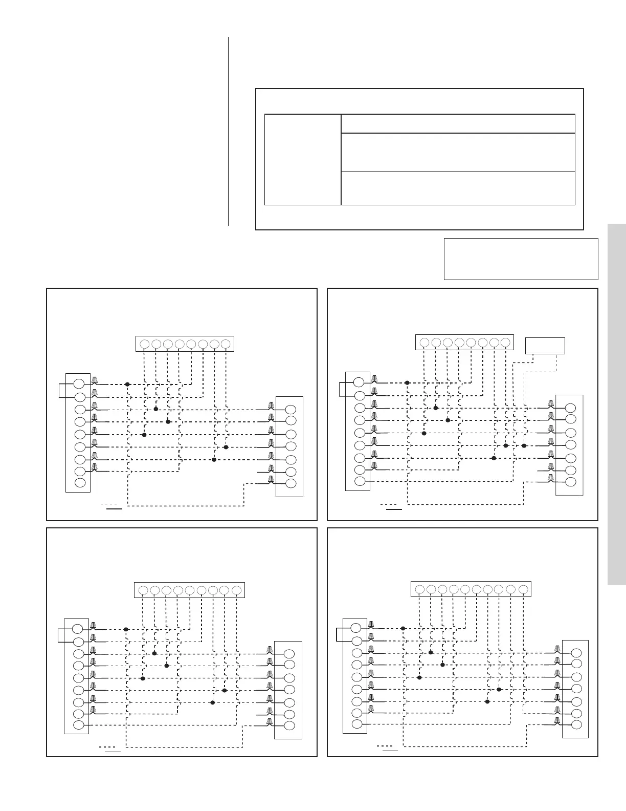
FIGURE 6
TYPICAL 2-STAGE THERMOSTAT: HEAT PUMP WITH ELECTRIC
HEAT
FIGURE 7
TYPICAL TWO-STAGE THERMOSTAT: (-)PRL HEAT PUMP WITH
ELECTRIC HEAT USING A HUMIDISTAT FOR DEHUMIDIFICATION*.
B
W2
W1
B
C
G
(-)HPL Air
H
andler
Y
1
E/W1
Typical Two-Stage Thermostat
(-)PRL
H
eat Pump
Outdoor
Unit
Y2
C
R
B
Y2
Field Installed
Line Voltage
-
WIRING INFORMATION
F
actory Standard
-
ODD
R
Y1
Y2
G
W
2
R
Y1
C
L
D
Y
Y
/BL
B
L
R
BR
W/R
P
R
Humidistat
*
FIGURE 8
TYPICAL TWO-STAGE THERMOSTAT: (-)PRL HEAT PUMP WITH
ELECTRIC HEAT USING A TWO-STAGE THERMOSTAT WITH
DEHUMIDIFICATION*
B
W2
W1
B
C
G
(-)HPL Air
Handler
Y1
E/W1
Typical Two-Stage Thermostat
(-)PRL
Heat Pump
Outdoor
Unit
Y2
C
R
B
Y2
Field Installed
Line Voltage
-
WIRING INFORMATION
Factory Standard
-
ODD
R
Y1
Y2
G
W2
R
Y1
C
L
D
Y
Y/BL
BL
R
BR
W/R
PR
DHM
*
B
W2
W1
B
C
G
(-)HPL Air
Handler
Y1
E/W1
Typical Two-Stage Thermostat
(-)PRL
Heat Pump
Outdoor
Unit
Y2
C
R
B
Y2
Field Installed
Line Voltage
-
WIRING INFORMATION
Factory Standard
-
ODD
R
Y1
Y2
G
W2
R
Y1
C
L
D
Y
Y/BL
BL
R
BR
W/R
PR
DHM
L
*
FIGURE 9
(-)PRL HEAT PUMP WITH ELECTRIC HEAT USING A TWO-STAGE
THERMOSTAT WITH DEHUMIDIFICATION* AND A MALFUNCTION
LIGHT
12.8 Typical Non-Communicating Thermostat Wiring Diagrams
WIRE COLOR CODE
B
K – BLACK G – GREEN PR – PURPLE Y – YELLOW
B
R – BROWN GY – GRAY R – RED
B
L – BLUE O – ORANGE W – WHITE
*See Section 5.11 for proper DIP switch selection.
The following figures show the typical wiring diagrams with (-)HPL air handler and (-)PRL heat
pump. Cooling and heat pump airflows may need to be adjusted for homeowner comfort once
the system is operational.
A thermostat and a 24-volt, 40VA minimum transformer are required for the control
circuit of the condensing unit. The furnace or the air handler transformer may be
used if sufficient. See the wiring diagram for reference. Use Table 6 to size the 24-
volt control wirings.
SOLID COPPER WIRE - AWG.
3.0 16 14 12 10 10 10
2
.5 16 14 12 12 10 10
2.0 18 16 14 12 12 10
50 100 150 200 250 300
Length of Run - Feet (1)
Thermostat Load - Amps
(1) Wire length equals twice the run distance.
N
OTE: Do not use control wiring smaller than No. 18 AWG between thermostat and outdoor unit.
TABLE 6
F
IELD WIRE SIZE FOR 24 VOLT THERMOSTAT CIRCUITS
CONVENTIONAL THERMOSTAT WIRING
29
*If maximum outlet temperature rise is desired, it is recommended that W1 and W2 be jumpered together.

 Loading...