13.0 ELECTRICAL WIRING
NOTE: Check all wiring to be sure connections are securely fastened, electrically
isolated from each other and that the unit is properly grounded.
Field wiring must comply with the National Electric Code (C.E.C. in Canada) and
any applicable local code.
13.1 Power Wiring
It is important that proper electrical power from a commercial utility is available at
the condensing unit contactor. Voltage ranges for operation are shown in Table 7.
Install a branch circuit disconnect within sight of the unit and of adequate size to
handle the starting current (see Table 1).
Power wiring must be run in a rain-tight conduit. Conduit must be run through the
connector panel below the access cover (see Figure 1) and attached to the bottom
of the control box.
Connect power wiring to line voltage lugs located in outdoor condensing unit electri-
cal box. (See wiring diagram attached to unit access panel.)
Check all electrical connections, including factory wiring within the unit and make
sure all connections are tight.
DO NOT connect aluminum field wire to the contactor terminals.
13.2 Grounding
A grounding lug is provided near the contactor for a ground wire.
13.3 Control Wiring
If the low voltage control wiring is run in conduit with the power supply, Class I insu-
lation is required. Class II insulation is required if run separate. Low voltage wiring
may be run through the insulated bushing provided in the 7/8 hole in the base
panel, up to and attached to the pigtails from the bottom of the control box. Conduit
can be run to the base panel if desired by removing the insulated bushing.
A thermostat and a 24 volt, 40 VA minimum transformer are required for the control
circuit of the condensing unit. The furnace or the air handler transformer may be
used if sufficient. See the wiring diagram for reference. Use Table 7 to size the 24
volt control wiring.
14.0 START-UP AND PERFORMANCE
Even though the unit is factory charged with Refrigerant-410A, the charge must be
checked to the charge table attached to the service panel and adjusted, if required.
Allow a minimum of 5 minutes of run time before analyzing charge.
At initial start-up or after extended shutdown periods, make sure the heater is ener-
gized for at least 12 hours before the compressor is started. (Disconnect switch on
and wall thermostat off.) Connect the communicating system per Figure 5. Once all
devices are connected, power up the line and low voltage to the system. When all
devices are powered, the thermostat should detect the indoor and outdoor units
within 45 seconds.
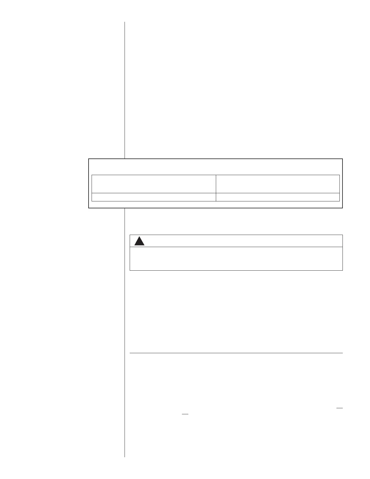
TABLE 7
V
OLTAGE RANGES (60 HZ)
Operating Voltage Range at Copeland
Nameplate Voltage Maximum Load Design Conditions for
Compressors
208/230 (1 Phase) 197 - 253
!
WARNING
THE UNIT MUST BE PERMANENTLY GROUNDED. FAILURE TO DO SO
CAN CAUSE ELECTRICAL SHOCK RESULTING IN SEVERE PERSONAL
INJURY OR DEATH.
36

 Loading...