CONVENTIONAL THERMOSTAT WIRING
12.9 ICC Control Operation with Conventional Thermostat Wiring
IInnssttaallllaattiioonn VVeerriiffiiccaattiioonn
• 24V AC power on R&C must be present at the ICC for it to operate
• Line voltage must be present at the ICC for the compressor and the outdoor fan
to operate
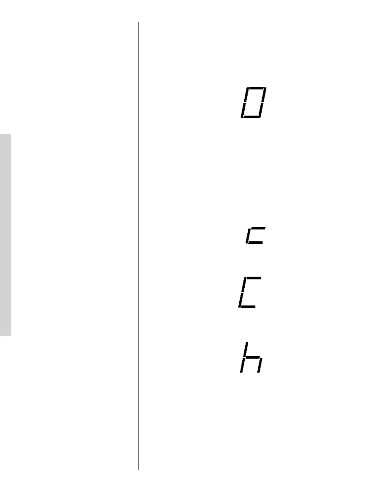
• The ICC displays a “0” for standby mode. Standby mode indicates line voltage
and 24VAC are present at the ICC and there is not a call for unit operation from
the thermostat.
Zero (0) displayed
The unit is in standby
CCaallll ffoorr CCoommpprreessssoorr OOppeerraattiioonn ((YY11 LLEEDD))
• If a call for compressor operation is received by the ICC (first stage/second stage
cooling or first stage/second stage heating), the red Y1 LED will illuminate.
• The ICC has an on/off fan delay of one (1) second for each stage of heating or
cooling.
• The ICC ignores the lower pressure control for the first 90 seconds of compressor
operation.
• On heat pumps, the ICC ignores the LPC during the defrost cycle.
• The dual 7-segment LED displays five (5) operational status codes:
11)) FFiirrsstt SSttaaggee CCoooolliinngg OOppeerraattiioonn
– When the ICC receives a call for first stage
cooling operation, a lower case “c” is displayed on the dual 7-segment LEDs.
Lower case “c” indicates first stage cooling operation
22)) SSeeccoonndd SSttaaggee CCoooolliinngg OOppeerraattiioonn
– When the ICC receives a call for second
stage cooling operation, an upper case “C” is displayed on the dual 7-segment
LEDs.
Upper case “C” indicates second stage cooling operation
33)) FFiirrsstt SSttaaggee HHeeaattiinngg OOppeerraattiioonn
- When the ICC receives a call for first stage
heating operation, “h” is displayed on the dual 7-segment LEDs.
“h” indicates first stage heating operation
2
Zero (0) displayed
The unit is in standby
Call for Compressor Operation (Y1 LED)
• If a call for compressor operation is received by the ICC (first stage/second stage cooling or
first stage/second stage heating), the red Y1 LED will illuminate.
• The ICC has an on/off fan delay of one (1) second for each stage of heating or cooling.
• The ICC ignores the lower pressure control for the first 90 seconds of compressor operation.
• On heat pumps, the ICC ignores the LPC during the defrost cycle.
• The 7-segment LED can display five (5) codes during a call for unit operation:
1) First Stage Cooling Operation – When the ICC receives a call for first stage cooling
operation, a lower case “c” is displayed on the 7-segment LEDs.
Lower case “c” indicates first stage cooling operation
2) Second Stage Cooling Operation – When the ICC receives a call for second stage
cooling operation, an upper case “C” is displayed on the 7-segment LEDs.
Upper case “C” indicates second stage cooling operation
3) First Stage Heating Operation - When the ICC receives a call for first stage heating
operation, “h1” is displayed on the 7-segment LEDs.
“h1” indicates first stage heating operation
4) Second Stage Heating Operation - When the ICC receives a call for second stage
heating operation, “h2” is displayed on the 7-segment LEDs.
1
13.X Conventional 24VAC Thermostat Control Wiring
T
he (-)PRL series of heat pumps allow the installer to use conventional 24VAC control wiring
and a conventional thermostat for proper unit operation.
IMPORTANT: The preferred method of unit installation and operation is by serial
communications. Serial communications allow access to the fault history of the system. This
d
iagnoistic information is not available when the (-)PRL unit is using a conventional thermostat.
R
eference section 13.3 Serial Communication Control Wiring.
Thermostat control wiring requires a minimum of six (6) wires for proper unit operation:
R
– 24VAC
C – 24VAC common
Y
1 – First stage operation
Y2 – Second stage operation
B
– Heat pump operation
D – Defrost
Optional wiring:
L – ICC fault information
If the low voltage control wiring is run in conduit with the power supply, Class I insulation is
required. Class II insulation is required if run separate. Low voltage wiring may be run through
t
he insulated bushing provided in the 7/8 hole in the base panel, up to and attached to the pigtails
from the bottom of the control box. Conduit can be run to the base panel if desired by removing
the insulated bushing.
A thermostat and a 24-volt, 40VA minimum transformer are required for the control circuit of
the condensing unit. The furnace or the air handler transformer may be used if sufficient. See
t
he wiring diagram for reference. Use Table 6 to size the 24-volt control wirings.
INSERT FIGURES 7 THRU 10 HERE FROM THE OLD
SECTION 13.4 HERE!!!!
13.X ICC Control Operation with Conventional Thermostat Wiring
Installation Verification
• 24V AC power on R&C must be present at the ICC for it to operate
• Line voltage must be present at the ICC for the compressor and the outdoor fan to operate
• The ICC displays a “0” for standby mode. Standby mode indicates line voltage and 24VAC
are present at the ICC and there is not a call for unit operation from the thermostat.
30

 Loading...