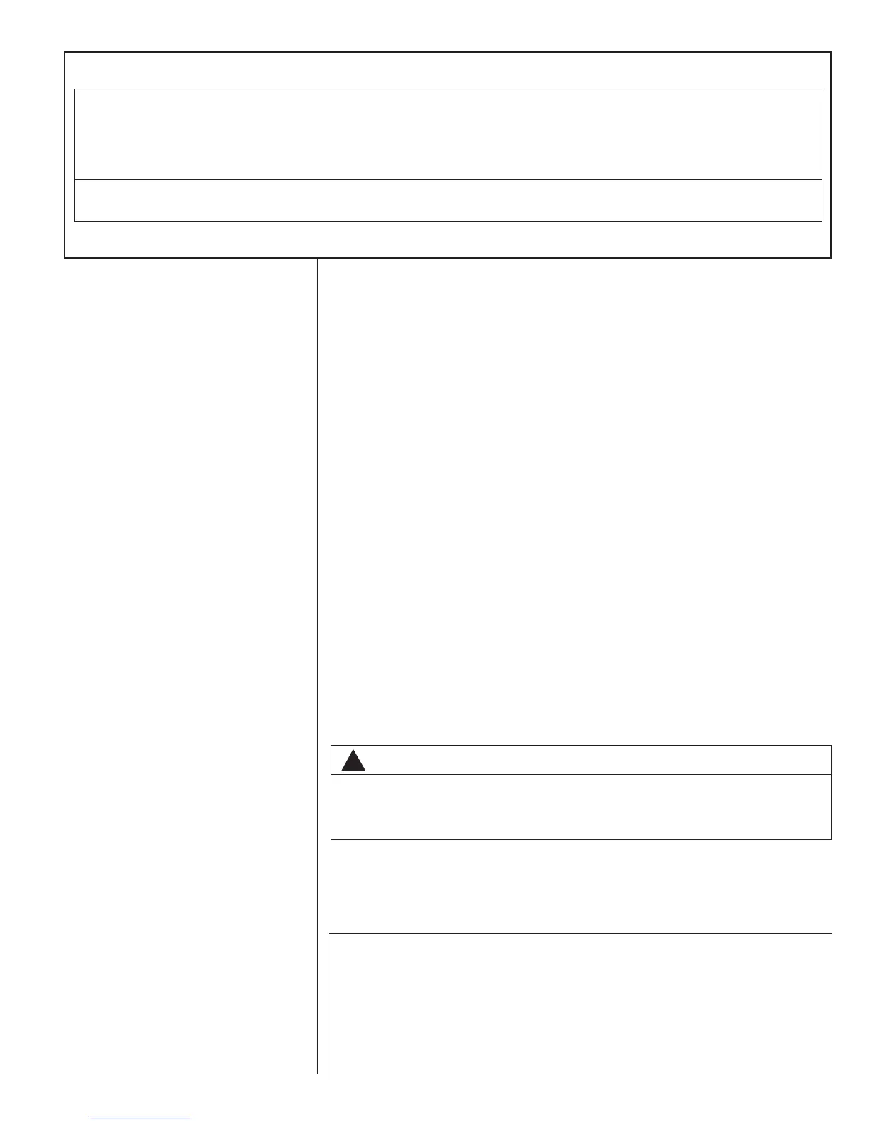
TABLE C
COPPER WIRE SIZE – AWG (1% VOLTAGE DROP)
17
300
250
200
150
100
50
Supply
Wire
Length
Feet
Circuit Ampacity
NOTE:
1. Wire size based on 60ºC type copper conductors below 100 ampacity. 2. Wire size based on 75ºC type copper conductors for 100 ampacity and above.
4
4
6
8
10
14
15
3
4
4
6
8
12
20
2
3
4
6
8
10
25
2
3
4
4
6
10
30
1
2
3
4
6
8
35
1/0
1
2
4
6
8
40
1/0
1
2
3
4
6
45
2/0
1/0
1
3
4
6
50
2/0
1/0
1
2
4
6
55
3/0
2/0
1/0
2
3
4
60
3/0
2/0
1/0
1
3
4
65
3/0
2/0
1/0
1
2
4
70
4/0
3/0
2/0
1/0
2
3
75
4/0
3/0
2/0
1/0
2
3
80
4/0
3/0
2/0
1/0
1
3
85
4/0
4/0
3/0
1/0
1
2
90
250
4/0
3/0
2/0
1
2
95
250
4/0
3/0
2/0
1
2
100
250
4/0
3/0
2/0
1
2
105
250
4/0
3/0
2/0
1/0
2
110
300
250
4/0
2/0
1/0
1
115
300
250
4/0
3/0
1/0
1
120
300
250
4/0
3/0
1/0
1
125
300
250
4/0
3/0
1/0
1
130
300
250
4/0
3/0
1/0
1/0
135
350
350
300
4/0
1/0
1/0
140
350
350
300
4/0
2/0
1/0
145
350
350
300
4/0
2/0
1/0
150
350
350
300
4/0
2/0
2/0
155
c. Clean and recoat aluminum conductor with inhibitor.
d
. Make the splice using the above listed wire nuts or split bolt connectors.
e. Coat the entire connection with inhibitor and wrap with electrical insulating tape.
WARRANTY MAY NOT APPLY IF CONNECTIONS ARE NOT MADE PER INSTRUC-
TIONS
C. CONTROL WIRING (Class II)
1. Low voltage wiring should not be run in conduit with power wiring.
2. Control wiring is routed through the 7/8" hole adjacent to the compressor access
panel. See Figure 2. Use a minimum #18 AWG thermostat wire. For wire lengths
exceeding 50', use #16 AWG thermostat wire. The low voltage wires are connected
to the unit pigtails which are supplied with the unit below the unit control box.
3. It is necessary that only heat pump thermostats be used.
4. Figure 18 shows representative low voltage connection diagrams. Read your ther-
mostat installation instructions for any special requirements for your specific thermo-
stat.
NOTE — Units installed in Canada require that an outdoor thermostat (30,000 min.
cycles of endurance) be installed and be wired with C.E.C. Class I wiring.
D. INTERNAL WIRING
1. A diagram of the internal wiring of this unit is located on the inside of the compres-
sor access panel. If any of the original wire as supplied with the appliance must be
replaced, the wire gauge and insulation must be the same as original wiring.
IMPORTANT: Some single phase units are equipped with a single pole contactor.
Caution must be exercised when servicing as only one leg of the power supply is bro-
ken with the contactor. Some models are equipped with electrically commutated blow-
er motors which are constantly energized unless the main unit disconnect is in the off
position.
E. GROUNDING
F. THERMOSTAT
The thermostat should be mounted on an inside wall about five feet above the floor in
a location where it will not be affected by unconditioned air, sun, or drafts from open
doors or other sources. READ installation instructions in heat pump thermostat pack-
age CAREFULLY because each has some different wiring requirements.
XIII. INDOOR AIR FLOW DATA
Direct-drive blower models are shipped factory wired for the proper speed at a typical
external static. Belt-drive blower models have motor sheaves set for proper CFM at a
typical external static.
!
WARNING
THE UNIT MUST BE PERMANENTLY GROUNDED. A GROUNDING LUG IS PRO-
VIDED IN THE ELECTRIC HEAT ACCESS AREA FOR A GROUND WIRE. FAILURE
TO GROUND THIS UNIT CAN RESULT IN FIRE OR ELECTRICAL SHOCK CAUS-
ING PROPERTY DAMAGE, SEVERE PERSONAL INJURY OR DEATH.
 Loading...