6
GENERAL INFORMATION
General Information
Proper Installation
Proper sizing and installation of this equipment is
critical to achieve optimal performance� Use the
information in this Installation Instruction Manual
and reference the applicable manufacturer’s
specification sheet when installing this product�
IMPORTANT: This product has been
designed and manufactured to meet ENERGY
STAR criteria for energy efficiency when matched
with appropriate indoor components� However,
proper refrigerant charge and proper airflow are
critical to achieve rated capacity and efficiency�
Installation of this product should follow the
manufacturer’s refrigerant charging and airflow
instructions� Failure to confirm proper charge
and airflow may reduce energy efficiency and
shorten equipment life�
MATCH ALL COMPONENTS:
• OUTDOOR UNIT
• INDOOR COIL
• INDOOR AIR HANDLER/FURNACE
• REFRIGERANT LINES
• INDOOR THERMOSTAT
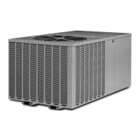
Specifications
RP14
18, 24, 30
25 (635)27 (686
9 (991)35 (889)
29.75 (756)33.75 (857) 35.75 (908)33.75 (857)
29.75 (756)
33.75 (857)
35.75 (908)33.75 (857)
Height “H” inches (mm)
Length “L” inches (mm)
Width “W” inches (mm)
36, 42 6048
“ L”
“W”
“H”
A
I
R
D
I
S
C
H
A
R
G
E
ALLOW 60” [1524mm]
OF CLEARANCE
AIR INLET LOUVERS ALLOW
6” [152mm] Min. OF CLEARANCE ALL SIDES
12” [305mm] RECCOMMENDED
SERVICE PANELS/
INLET CONNECTIONS / HIGH & LOW
VOLTAGE ACCESS
ALLOW 24” [ 610 mm] OF CLEARANCE
ST-A1226-02-00
ALLOW 60" [1524mm] OF
CLEARANCE
SERVICE PANELS/
INLET CONNECTIONS /
HIGH & LOW VOLTAGE
ACCESS ALLOW
24" [610 mm] OF
CLEARANCE
AIR INLET LOUVERS ALLOW
6" [152 mm] OF CLEARANCE ALL SIDES
12" [305 mm] RECOMMENDED

 Loading...