The provided document is an owner's manual for the Ride1Up CORE-5 e-bike, offering comprehensive instructions for assembly, operation, maintenance, and troubleshooting.
Function Description
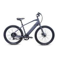
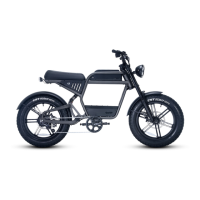
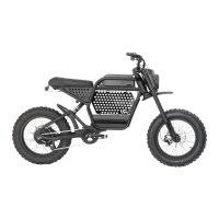
The Ride1Up CORE-5 is an electric bicycle designed for use on paved roads and smooth surfaces. It provides pedal assist (PAS) with multiple levels and a throttle for additional power, making cycling easier and more accessible. The e-bike is equipped with a motor, battery, and display unit to manage its electrical functions. It is intended for riders aged 18 and older and has a maximum permitted overall weight (rider + cargo) of 300 lbs.
Usage Features
Assembly and Initial Setup:
The manual guides users through the assembly process, starting with the fork and headset. It emphasizes checking cable and wire routing, ensuring the fork is correctly oriented (brake caliper on the left), and properly seating the compression ring and headset spacers. The stem and handlebars are then installed, with a critical warning to tighten the bar clamp and compression cap correctly to prevent movement and ensure safety.
Next, the front wheel assembly involves aligning the disc rotor between the brake pads and securing the axle nuts to 35nm of torque. Users are warned not to touch brake pads or rotors with fingers to avoid contamination and noise.
The seat post assembly requires opening the seat clamp, inserting the seat post past the minimum insertion point, and then adjusting the height before tightening the clamp. For models where the seat post and saddle are separate, the saddle is slid into the seat post clamp, and the bolt is tightened to 16-17nm, ensuring proper groove alignment.
Pedal assembly involves applying grease to the bottom bracket spindles. The left pedal (marked "L") is reverse-threaded and installed counterclockwise, while the right pedal (marked "R") is standard-threaded and installed clockwise. Both should be screwed in by hand initially and then tightened with an adjustable wrench. A crucial note highlights that using the correct pedal on the correct side is vital to prevent stripping the crank arm.
Battery Operation:
The battery is connected and removed by inserting the key, turning it clockwise 90 degrees, and then pulling out the battery. When replacing, the key should be in the same position before turning it to lock. The battery's charger port is on the upper right and must always be covered to protect against moisture.
Charging the Battery:
Charging involves turning off the bike and LCD, plugging the charger into a socket, and then inserting the charger plug into the battery. Users are advised to ensure the charger's tip is not stressed or supporting the charger's weight and not to wiggle it. The battery's LED lights indicate charging status: red for charging and green for fully charged. Charging typically takes 3-6 hours with the standard charger. Important safety warnings include not leaving the battery unattended while charging, not storing batteries connected to the charger, and not wiggling the charger tip in the port. The battery should be charged in an ambient temperature, on a non-flammable, dry surface, away from heat, humidity, or flammable materials, and uncovered.
Display Instructions (KD21C LCD):
The display unit provides information such as battery voltage (indicated by 3 colors: blue for full, green for half or less, red for low), speed, mileage, and assist level.
- Power On/Off: Press and hold the MODE button for 2 seconds. The display automatically shuts down after 10 minutes of inactivity. For safety, it's recommended to turn the bike on only after straddling the frame and to turn it off before dismounting or when stopping to talk.
- Pedal Assist Level Operating: Assist levels range from "0" (no assist) to "5" (maximum power). Levels are changed using the UP or DOWN buttons.
- Speed & Mileage Mode Switch: Pressing the MODE button cycles through running speed, trip distance, trip time, maximum speed, average speed, and motor power.
- Backlight On/Off: Press and hold the UP button for 2 seconds to toggle the display backlight and headlights (if wired).
- Walk/Push Assist (4mph): Press and hold the DOWN button for 2 seconds to activate walking mode.
- Change Settings: Holding both UP and DOWN buttons for 2 seconds accesses general settings. The MODE button saves settings and exits, while the DOWN button cancels without saving. Settings can only be accessed when the e-bike is parked.
Derailleur and Shifter Adjustment:
The manual notes that derailleurs may need tuning after initial assembly or after some miles of riding, especially if shifting is noisy, not smooth, or the chain shifts past the largest or smallest cog. It highlights the critical importance of properly adjusting the low and high limit screws to prevent the chain from damaging the derailleur, hanger, motor cable, spokes, and rim, especially given the motor's power.
Brake Adjustment:
After assembly, both front and rear brakes must be tested and adjusted. The front wheel and brake caliper installation can affect disc brake rubbing. Users should align the disc rotor in the exact middle between the pads while tightening axle nuts. If the disc rotor is bent (common during shipping), it can sometimes be trued or replaced.
Maintenance Features
General Maintenance:
- Regular Inspections: Owners are responsible for properly assembling the bike and regularly inspecting all components, ensuring all nuts and bolts are securely tightened. This is crucial for safety and warranty coverage.
- Professional Checks: The e-bike should be regularly checked at a professional bike shop, and any worn parts should be replaced.
- Tire Pressure: Regularly check tire pressures according to the sidewall's recommended psi range.
- Tread Depth: Regularly check the tread depth of tires.
- Post-Accident Inspection: After an accident or crash, the e-bike must be taken to a bike repair specialist for inspection, as damage may not be visible.
- Part Replacement: Always use genuine replacement parts for maintenance. Any cracks, scratches, or color changes in highly stressed areas indicate that a part has reached its life expectancy and should be replaced immediately.
Electrical System Maintenance:
- Charger Use: Only use the charger supplied by Ride1UP. Never modify the charger. Check the charger cord for damage before use.
- Battery Storage: Do not store the bike or battery plugged into a wall outlet. Unplug the battery before leaving the bike alone. For extended life, store the battery with a 40-80% charge and check it monthly, recharging to 40-80% if it drops below 25%. Recommended storage temperatures are 50°-77°F in a dry area.
- Moisture Protection: Always keep the battery's charge port covered to protect against moisture.
Brake Maintenance:
- Regular Checks: Regularly check brakes for signs of wear and tear and functionality. Test brakes before every ride.
- Pad/Rotor Care: Ensure braking surfaces and brake pads are free of wax, grease, and oil.
Spoke Tension:
The manual provides a table with recommended spoke tensions (in KGS and Park tools units) for the front-left, front-right, rear-left, and rear-right spokes, indicating the importance of maintaining proper spoke tension for wheel integrity.
Troubleshooting:
The manual includes an error code troubleshooting section for electrical components. If an error code appears on the display, users can refer to the list to identify the source of the error and potential solutions. For example:
- Error 21 (Current Abnormality): Indicates the battery is not supplying the required voltage. Users can check the real-time voltage on the display or with a multimeter.
- Error 22 (Throttle Abnormality): Suggests the throttle is not returning to its original position or the cable is damaged.
- Error 23 (Motor Sensor): Points to a loose or contaminated connection of the rear hub motor cable.
- Error 24 (Motor Communication): Indicates a problem with the motor cable connection to the chainstay or internal controller.
- Error 25 (EBS - Electronic Brake Shut-off): Likely a magnet sensor issue, often after a crash.
- Error 30 (Communication Error): Signifies a problem with the connection between the internal controller and the display.
Warranty Claims:
The warranty covers product defects present at the time of handover for one year. It does not cover normal wear and tear, misuse, accidents, or modifications. For shipping damage, Ride1UP will file a claim and send replacement parts. For other warranty claims, owners must send an email with photos/videos to support@ride1up.com. After 30 days, owners are responsible for labor costs for warranty part replacements.