声明:本说明书著作权归杭州睿登科技有限公司所有,未经允许任何单位或个人不得用于商业用途。
7
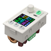
R: Power source input interface
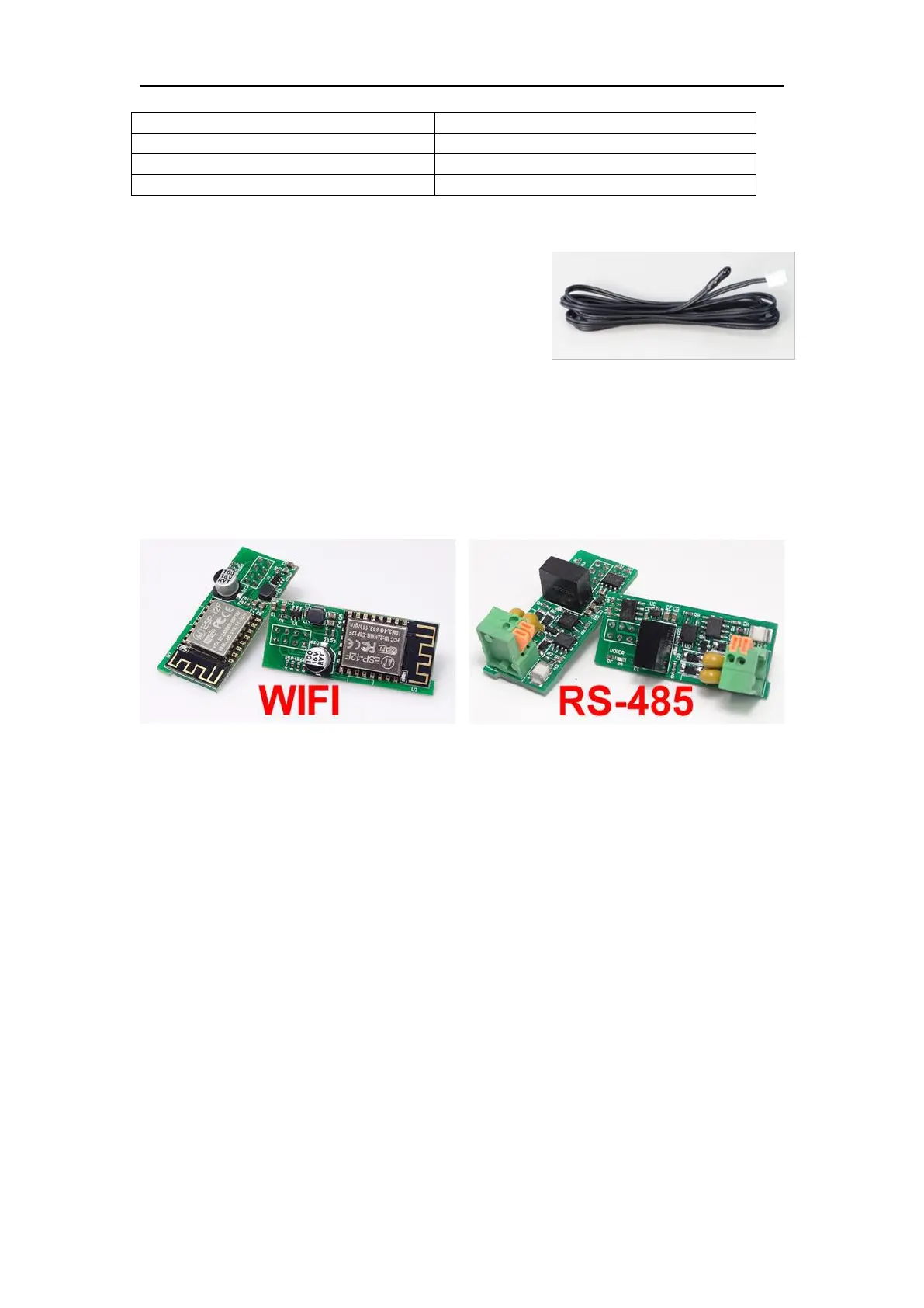
S: External temperature sensor interface
U: Communication module interface
NOTE:
Power source input interface must be
connected to 6-70V constant DC power source. The
external sensor cable (as shown on right) must be
connected to the external temperature sensor
interface. The fan interface cannot be connected to
other fans. When the system temperature is higher than 80 ℃ , the output will be
shut down and show OTP on the scrren. CR1220 is the clock battery (Please prepare
by yourself), it can power on the clock function. Communication interface is a special
interface, please don’t connect to other modules or cables.
You can see the Wi-Fi module and RS-485 module in the picture below. If you
need RS-485 for industrial batch test and it is not on sale now, if you want to use that,
please contact us.
1.4 Operation Instruction
After power-on, it will show boot image first, and then enters the main page.
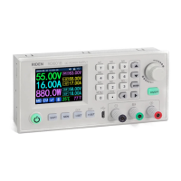
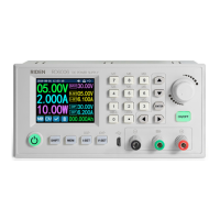
We use RD6012 as example to introduce how to use it.