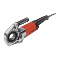
Self-Opening Die Heads
The Model 815A Die Heads are self-opening die heads.
For
1
/
2
" through 2" pipe sizes, a trigger can be used to open
the die head when the thread is complete. For
1
/
8
" to
3
/
8
"
sizes, bolt and straight threads, and if desired for the
other sizes, the die head is manually opened when the
thread is complete.
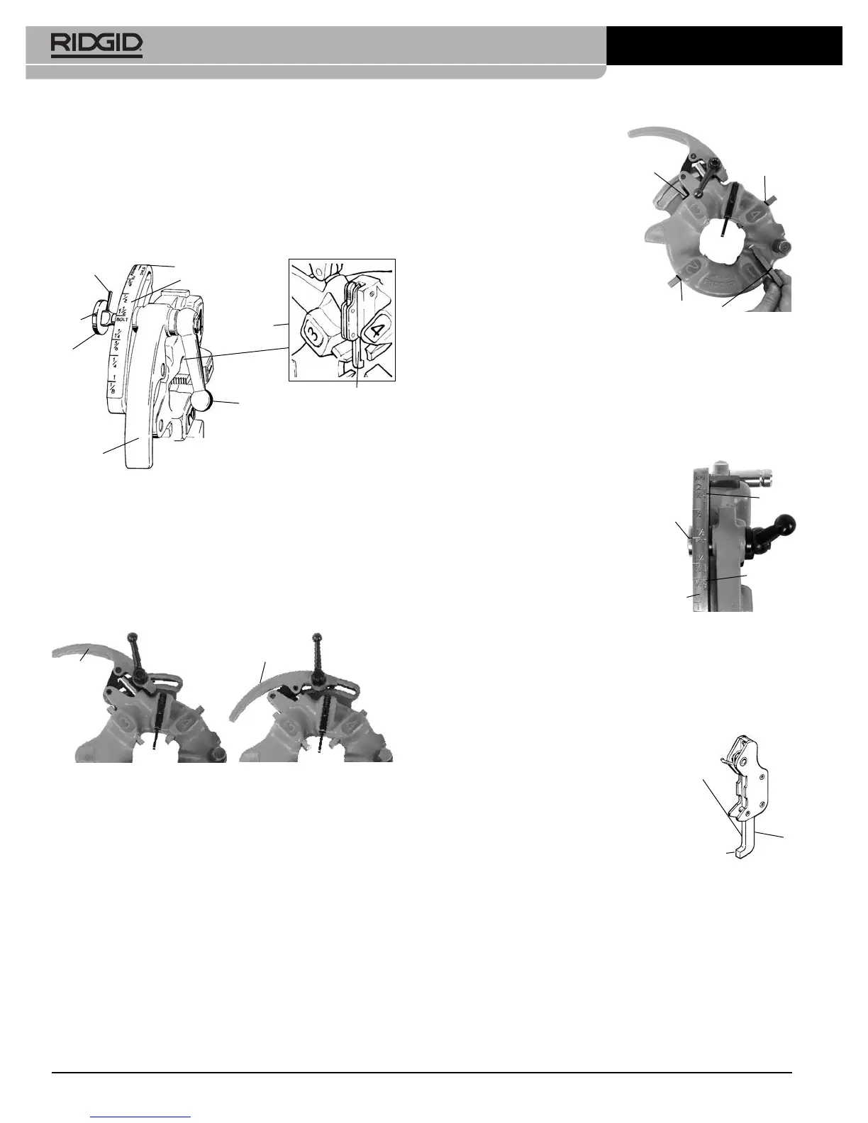
Figure 10 – Universal Self-Opening Die Head
Inserting/Changing the Dies
1. Place the die head with numbers facing up.
2. Make sure the trigger assembly is released and die
head OPEN by pulling the trigger slide away from the
die head. Stay clear of the spring loaded Throwout
Lever while releasing trigger assembly.
Figure 11 – Open/Closed Position
3. Loosen clamp lever ap proximately six full turns.
4. Pull lock screw out of size bar slot so roll pin will
bypass slot. Position size bar so that the index line on
lock screw is a ligned with the RE MOVE DIES mark.
5. Remove dies from the die head.
6. Insert appropriate dies into the die head, numbered
edge up until the indicator line is flush with the edge of
the die head (see Fi gure 12). Num bers on the dies
must cor res pond with those on the die head slots.
Always change dies as sets – do not mix dies from dif-
ferent sets.
7. Move size bar so in dex
line on lock screw is a -
ligned with desired size
mark. Adjust die insertion
as needed to allow move-
ment.
8. Make sure roll pin points
to ward REMOVE DIES
mark.
9. Tighten the clamp lever.
Adjusting Thread Size
1 Install the die head per the Thread ing Machine Instruc -
tions and move the die head into threading position.
2. Loosen clamp lever.
3. Position size bar so index line on lock screw is aligned
with desired size mark on size bar.
4. If thread size needs to be ad -
justed, set the lock screw index
line slightly off the mark on size
bar in the direction of OVER
(larger dia meter thread, less
turns of fitting engagement) or
UNDER (smaller thread dia -
meter, more turns of fitting en -
gagement) markings.
5. Tighten clamp lever.
Trigger Slide Adjustment
Position the Trigger Slide for the size of pipe being thread-
ed (see Figure 14).
•
1
/
2
" and
3
/
4
" – End of pipe should hit foot of Trigger
Slide.
• 1" to 2" – End of pipe should hit
the shank of the Trigger Slide.
For
•
1
/
8
", ¼" and
3
/
8
" pipe
• Longer or shorter threads
• Bolt threading
Push trigger slide up and out of the
way. Die head must be opened man-
ually.
Opening the Die Head at the End of the Thread
When using trigger it will contact the end of pipe, causing
the die head to automatically open. Stay clear of the
spring loaded Throwout Lever when it releases.
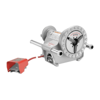
10
300 Compact/1233 Threading Machines
Throwout
Lever
Open
Closed
Throwout
Lever
Figure 12 – Inserting Dies
Indicator Line
Indicator
Line
Indicator
Line
Figure 13 – Adjusting
Thread Size
Lock
Screw
Index
Line
Size
Bar
“Over”
“Under”
Throwout
Lever
Trigger
Assembly
Clamp Lever
Size Bar
Roll Pin
Index
Line
Lock
Screw
“Remove Dies” Mark
Trigger
Slide
1" thru 2"
pipe hit
this
surface
Trigger
Slide
1
/
2
" and
3
/
4
"
pipe hit this
surface
Figure 14 – Setting
the
Trigger