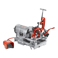
when end of pipe is plus or minus one turn of being
flush with face of ring gage.
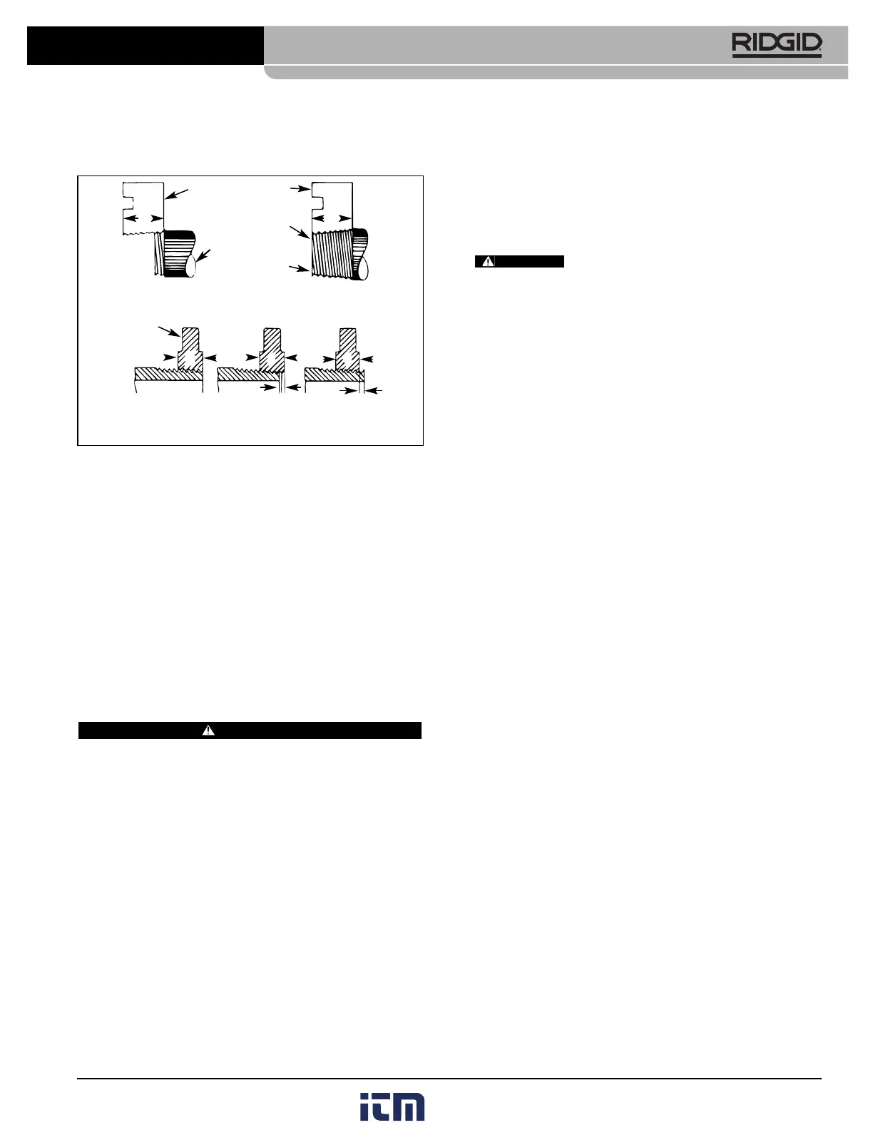
Figure 11 – Checking Thread Length
NOTE! If a ring gage is not available, a fitting can be
used. This fitting should be representative of
those being used on the job. The pipe thread
should be cut to obtain 2 or 3 turns hand tight
engagement with fitting. If pipe thread is not prop-
er diameter the index line should be moved in the
direction of the OVER or UNDER size mark on
size bar. (Refer to “Installing Dies In Die Heads”).
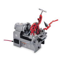
Priming Oil Pump
Current 535 Machines have a self-priming gerotor-type
pump. Machines made prior to June 1, 1996 have a
Model A vane-type pump that may require priming.
WARNING
All 535 Threading Machines made prior to June 1, 1996
should have a tube extension on the oil pump priming
port, as well as a top cover access hole, so the pump can
be primed without removing the top cover of the machine.
This will prevent the operator from contacting the internal
gearing of the machine which could result in serious injury.
To prime the Model A Pump, the following procedure
should be followed:
1. Remove button plug located on cover.
2. Remove primer screw through opening with allen
wrench.
3. Fill pump with oil.
11
4. Replace primer screw and button plug before starting
machine or pump will drain itself immediately.
NOTE! If machine must be primed on a frequent basis,
it is an indication the pump is in need of repair.
Accessories
Only the following RIDGID products have
been designed to function with the 535 Threading
Machine. Other accessories designed for use with other
tools may become hazardous when used on this
Threading Machine. To prevent serious injury, use only
the accessories listed below.
Accessories For Threading Machine
Die Head Racks:
4U ...........................holds 4 heads
6U ...........................holds 6 heads
Stands:
No. 100A.................4 legs w/tray
No. 150A.................2 wheels w/tray
No. 200A...................2 wheels w/enclosed cabinet
Pipe Supports:
VJ-99 ......................28
1
/
4
″ –52
1
/
2
″
RJ-99 ......................30
1
/
2
″ –54
3
/
4
″
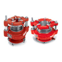
No. 819 Nipple Chuck (Right Hand only):
Pipe Adapters...........
1
/
8
″ through 1
1
/
2
″
Stud Adapters..........
1
/
4
″ through 2″ UNC
1
/
4
″ through 1
1
/
2
″ UNF
Model MJ-1 Pump Kit for Left Hand Threading
Accessories for Threading By Close-Coupled
Method
Drive Link Assembly (Cat. # 42415 or 16723
depending on carriage)
No. 844 Drive Bar
Saddle Adapter for Model 141
No. 141 Geared Threader for 2
1
/
2
″ – 4″ Threading
VJ-99/RJ-99 Pipe Support Stand
Accessories for Threading with Drive Shaft
No. 840A Universal Drive Shaft (41″ closed, 50″
extended)
No. 460 Tristand Chain Vise
No. 418 Oiler
VJ-99/RJ-99 Adjustable Pipe Support
Nos. 141 Geared Threader 2
1
/
2
″ to 4″ Threading
No. 161 Geared Threader 4″ to 6″ Threading
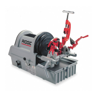
535 Manual Pipe and Bolt Threading Machine
WW
D
D
D
Die
Pipe
Die
Pipe
A - Full Width Die Thread
Starting to Cut Thread
Flush
(Basic Size)
One Turn Large
(Maximum Size)
One Turn Small
(Minimum Size)
Thin Ring
Gage
Completed Thread
Die Flush
With End
of Pipe
B - Checking Threads Within Pipe Gage
WARNING