5
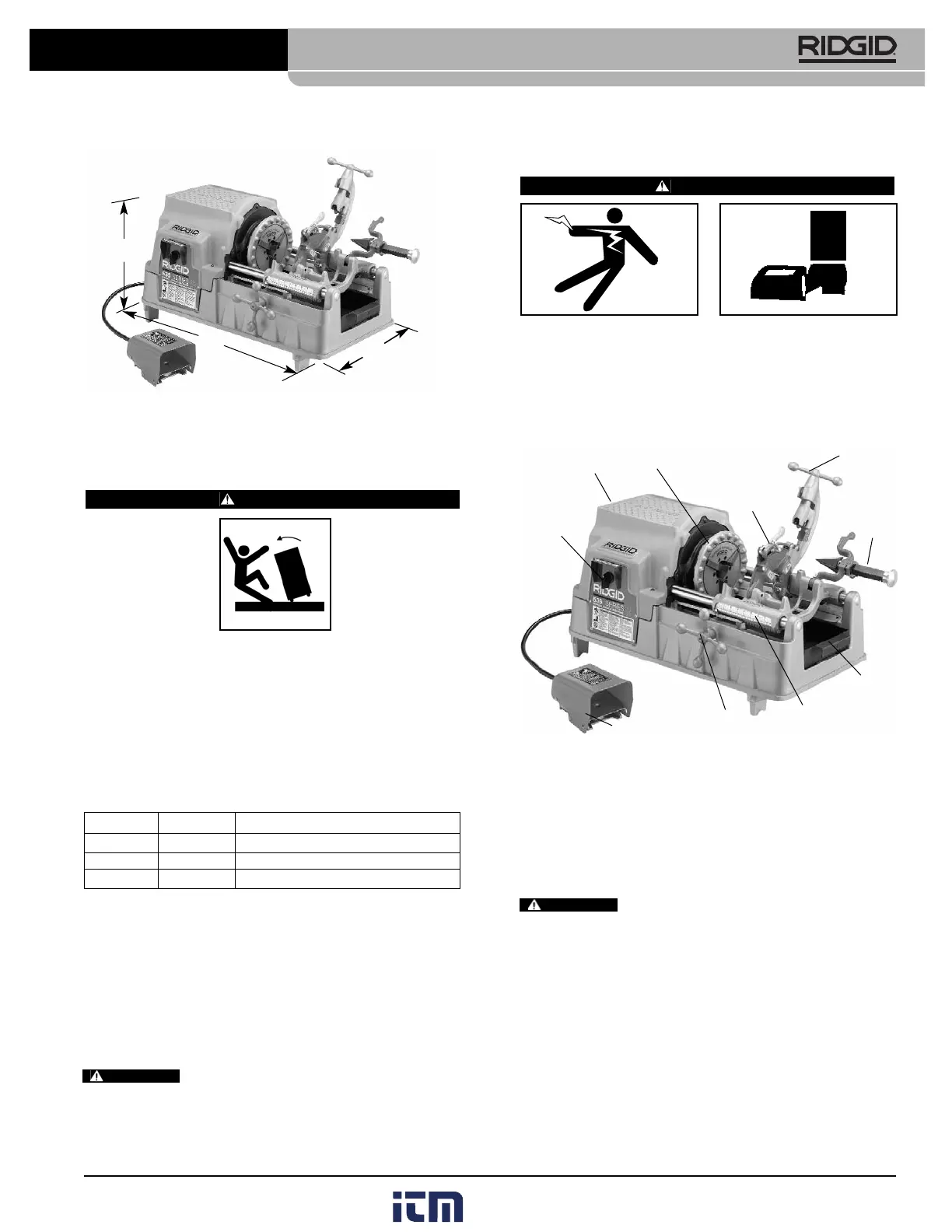
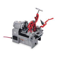
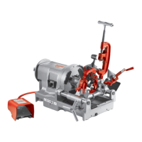
Figure 2 – No. 535 Machine Dimensions
Machine Assembly
WARNING
To prevent serious injury, proper assembly of the
Threading Machine is required. The following pro-
cedures should be followed:
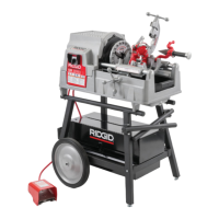
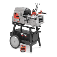
Mounting Machine To Stand
1. The machine is designed to mount on the three uni-
versal stands listed below.
Figure 3
Mounting Machine To Bench
1. If a stand is not used, the machine should be mount-
ed to a stable bench. To mount the unit on a bench,
use four (4)
5
/
16
″ bolts in holes provided at each corner
of machine base. Base dimensions are shown in
Figure 2
.
Failure to mount the threading machine to
a stable stand or bench may result in tipping and serious
injury.
Machine Inspection
WARNING
To prevent serious injury, inspect your Threading
Machine. The following inspection procedures
should be performed on a daily basis:
1. Make sure Threading Machine is unplugged and the
directional switch is set to the OFF position
(Figure 4)
.
Figure 4 – No. 535 Pipe and Bolt Threading Machine
2. Clean the speed chuck jaws with a wire brush.
3. Inspect the jaw inserts for excessive wear. Refer to the
Maintenance Instructions if they need to be replaced.
4. Make sure the foot switch is present and attached to
the Threading Machine
(Figure 4)
.
Do not operate the Threading Machine
without a foot switch.
5. Inspect the power cord and plug for damage. If the
plug has been modified, is missing the grounding
pin or if the cord is damaged, do not use the
Threading Machine until the cord has been replaced.
6. Inspect the Threading Machine for any broken, miss-
ing, misaligned or binding parts as well as any other
conditions which may affect the safe and normal
operation of the machine. If any of these conditions
are present, do not use the Threading Machine until
any problem has been repaired.
535 Manual Pipe and Bolt Threading Machine
WARNING
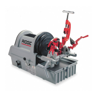
Machine Stands
Model No. Cat. No. Description
100A 92457 Universal Leg & Tray Stand
150A 92467 Universal Wheel & Tray Stand
200A 92462 Universal Wheel & Cabinet Stand
20.8″
38.1″
20.5″
Centering
Device
(Not Shown)
Chuck Handwheel
Quick or
Self-Opening
Die Head
No. 820
Cutter
(Standard)
No. 341
Reamer
Chip
Pan
REV/OFF/FOR
Switch
Foot Switch
Carriage Handwheel
Length Gauge
WARNING