Ridge Tool Company
5
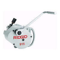
915 Roll Groover Set-up
IMPORTANT! To confirm the proper groove depth, test
grooves should be performed and checked
with a Pi tape.
1. At a bench or on the ground, rotate the feed screw
counter clockwise to “open” the groove roll from
the drive roll
(Figure 2)
.
Figure 2 – “Open” Groove Roll from Drive Roll.
NOTE! Ensure that groove set specifications matches
pipe/tube capacity to be grooved. See drive roll
for capacity.
IMPORTANT! Do not attempt to groove copper tube with
the steel groove set. Also do not attempt to
groove steel with copper groove rolls.
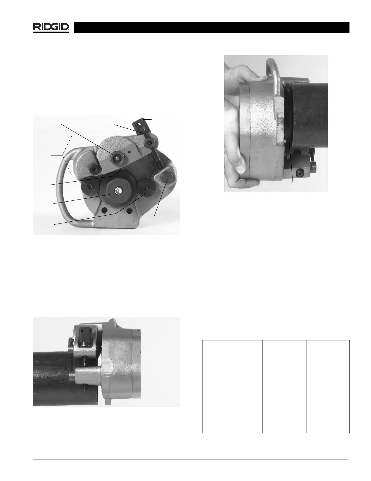
2. Place 915 onto pipe/tube with feedscrew accessible
(Figure 3)
.
Figure 3 – Placing Groover on Pipe
3. Push 915 into pipe/tube until fully engaged. End of
pipe should contact the drive roll flange
(Figure 4)
.
Figure 4 – Pipe Contact with Drive Roll Flange
4. Rotate the feed screw clockwise by hand until tight.
915 should now be held in position on the pipe/tube.
Adjusting for Groove Depth
NOTE! The groove depth must be adjusted for each
pipe/tube diameter and wall thickness.
1. With feedscrew handtight, run depth adjustment
screw down until it touches the pivot nut.
2. Back the depth adjustment screw off the number of
turns indicated in
Chart 1 (For Steel/Stainless Steel,
For Copper See Chart 2. These are approximate set-
tings only).
NOTE! The distance between the depth adjustment
screw and the pivot nut equals roll groove depth.
Adjustments up or down, with test grooves, will
ensure proper groove depths for couplings.
Chart 1 – Depth Adjustment for Steel/Stainless Steel
915 In Place Roll Groover
Groove Roll
Shaft
Feedscrew
Reaction
Arm
Groove
Roll
Drive
Roll
Stabilizer
Pads
Pivot
Nut
Depth
Adjustment
Screw
Drive Roll Flange
Steel/Stainless Steel Sch. 10 Sch. 40
Pipe Diameter Turns Turns
1
1
/
4
″ 3
3
/
4
4
1
1
/
2
″ 3
3
/
4
4
2″ 3
3
/
4
4
2
1
/
2
″ 4
3
/
8
5
3
/
8
3″ 4
3
/
8
5
5
/
8
4″ 4
5
/
8
6
7
/
8
6″ 57
1
/
2
8″ 6N/A
10″ 6
1
/
4
N/A
12″ 7
1
/
2
N/A
 Loading...