Ridge Tool Company
9
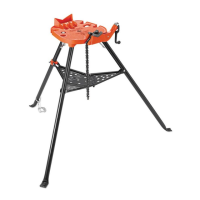
Figure 15 – Removing Feedscrew
4. Using a
1
/
8
″ hex key, remove set screw in reaction
arm and remove groove roll shaft.
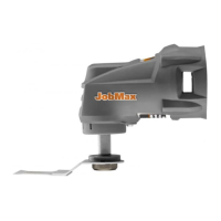
5. Remove groove roll and thrust washers from reaction
arm.
6. Remove feedscrew from pivot pin. Remove pivot
pin from reaction arm
(Figure 16)
.
7. Remove the hex screw retaining the drive roll with a
5
/
16
″ hex key. If removing the 4″ – 6″ Sch. 40 or 8″ – 12″
Sch. 10 roll set, remove the drive roll support bolts
using a
3
/
8
″ hex key
(Figure 16)
.
8. Remove stabilizer pad on the handle side of the 915
using a
3
/
16
″ hex key. If removing the 8″ – 12″ Sch. 10
roll set remove both stabilizer pads
(Figure 16)
.
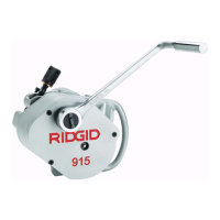
Figure 16 – Parts Call Out
Installing Copper Roll Set
1. Install copper stabilizer pad on handle side of 915
groover using the
3
/
16
″ hex key (Opposite side stabilizer
should be standard 2″ – 6″ Sch. 10 stabilizer pad.)
(Figure 17)
.
Figure 17 – Installing Copper Stabilizer Pad
2. Place the copper drive roll over driveshaft. Be sure
that the drive roll flange contacts the bronze thrust
washer.
3. Insert the hex screw into the drive roll and tighten with
5
/
16
″ hex key.
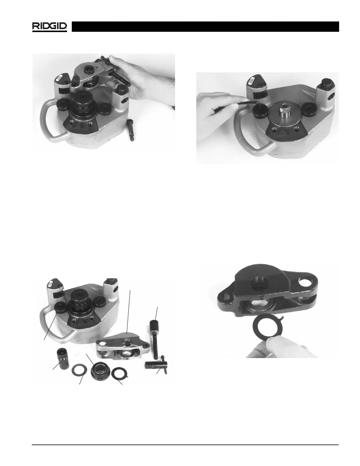
4. Using the copper reaction arm (painted black), place
the plain thrust washer at the back of the reaction arm
slot. Place the tabbed thrust washer in the front of the
reaction arm slot with the tab inserted in the small
hole to the right of the groove roll shaft
(Figure 18)
.
Figure 18 – Inserting Tabbed Thrust Washer
5. Slide the groove roll between the thrust washers in
the reaction arm. Be sure that the groove roll is
properly oriented with the identification stamping in
the “up” position.
6. Look through the groove roll shaft hole and align
the groove roll and thrust washers with the hole.
Insert groove roll shaft.
915 In Place Roll Groover
Reaction Arm
Feedscrew
Pivot Nut
Tabbed Thrust Washer
Plain Thrust Washer
Groove
Roll Shaft
Groove
Roll
Handle
Side
Stabilizer
Pad
 Loading...