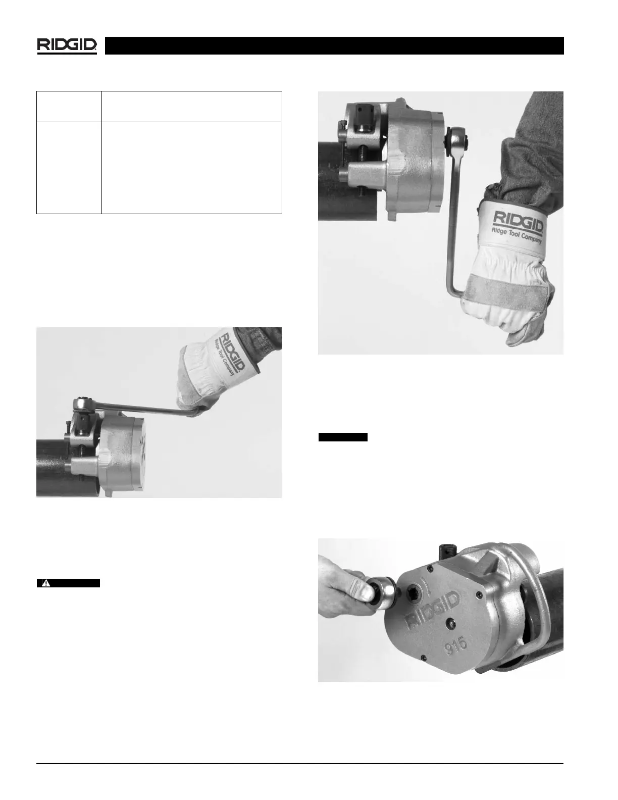
Figure 6 – Grooving pipe
4. Disconnect ratchet from input drive and place in
feedscrew.
5. Tighten feedscrew
1
/
2
turn.
Under or over tightening the feed screw could
result in the 915 “walking” off or slipping inside the pipe.
6. Repeat steps 3 – 5 until depth adjustment screw
touches the pivot nut.
7. Move ratchet from feedscrew to input drive
(Figure 7)
.
Turn ratchet to rotate 915 around pipe/tube two rev-
olutions to complete groove and ensure uniformity.
Figure 7 – Ratchet in Input Drive
Ridge Tool Company
6
Chart 2 – Depth Adjustment for Copper Tubing
NOTE! 1 turn depth setting screw = approximately
.020″ change in groove depth (.040 change in
groove diameter).
Forming the Groove
1. Place the ratchet into feedscrew
(Figure 5)
.
Figure 5 – Ratchet in Feedscrew
2. Tighten feedscrew 1
1
/
2
turns. Be sure pipe is still
flush with drive roll flange.
IMPORTANT! Extreme pressure caused by over ratch-
eting will cause distortion to thin wall pipe.
Do not use power actuated devices
(drills, power drives, impact wrenches, etc.) to drive
the 915 roll groover!
3. Move ratchet from feedscrew to input drive. Turn
ratchet to rotate 915 around pipe/tube one revolution
(Figure 6)
.
915 In Place Roll Groover
WARNING
CAUTION
Cut Tube # of Screw Turns
Size K L M DWV
2″ 2 2 1.75 N/A
2
1
/
2
″ 2 2 1.75 N/A
3″ 2.25 2.25 2 2
4″ 3 2.75 2.75 2.5
5″ 4.25 3.75 3.5 3.25
6″ 4.75 4 3.75 3.25
8″ 6.5 4.75 4.25 3.5