29
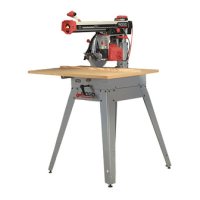
3. Lower arm until saw blade just clears the
front table. Tighten the yoke lock lever and
bevel lock lever.
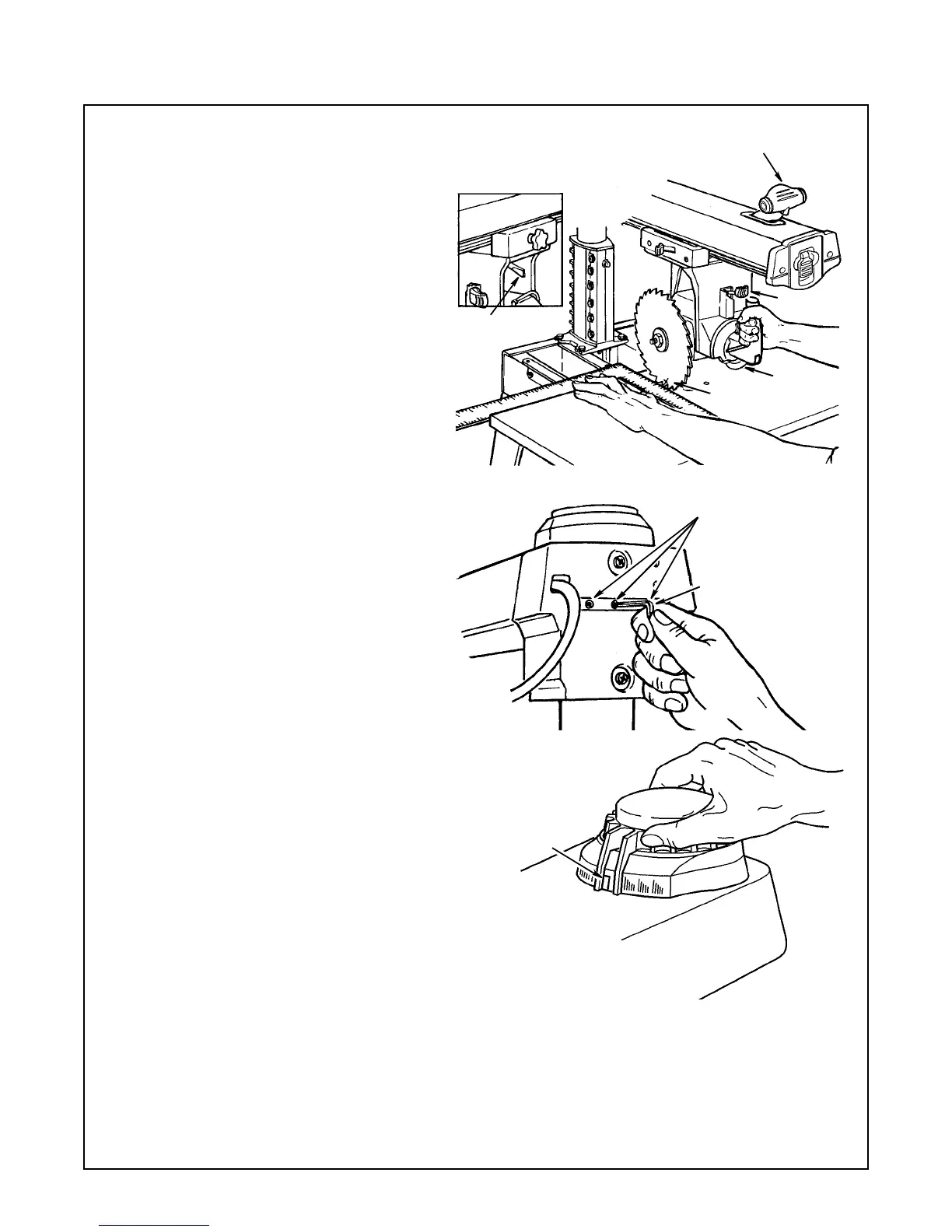
4. Place a framing square on the table, as
shown, with one leg of square firmly against
rear edge of front table. Position the blade
and square until the leg of the square just
contacts a tooth of the blade. Mark this
tooth.
5. When the carriage is moved slowly back
and forth on the arm, the marked tooth
should just touch the square at all points. If
marked tooth moves into or away from
square the following adjustments are
required:
a. Loosen (3) 3/8 - 16 set screws in arm
latch at rear of arm as shown.
b.Movethearmindirectiontomake
marked tooth follow edge of square when
the saw blade is moved along arm in a
“cross cut" manner.
c. Lock miter/arm lock lever.
d. Retighten (3) setscrews in arm latch as
tight as possible and recheck "cross cut"
travel.
Note:
This squaring of the cross cut travel will simul-
taneously set both of the 45° miter index positions.
6. Set miter indicator on 0° position as
shown.
Miter/Arm Lock Lever
Yoke Lock
Lever
Marked
Tooth
Bevel Lock
Lever
Bevel Index
Lever
3/16" Hex “L” Wrench
(Supplied)
Loosen Three
Set Screws
Rotate Miter
Indicator To
0° Position
Alignment
 Loading...