Do you have a question about the Riello UPS MPX 130 PWC and is the answer not in the manual?
Read the safety manual before any operations.
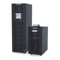
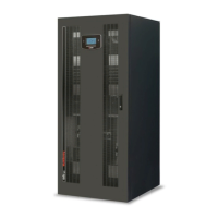
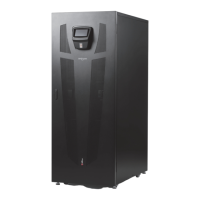
Overview of the MPX modular UPS system's features.
Diagram showing the front view with labeled components.
Diagram showing the front view with labeled components.
Describes the On Line double conversion mode.
Cautions regarding service, maintenance, and handling.
Overview of hot-swap modules and units for installation.
Explanation of backfeed protection and BM model actions.
Procedures for inserting/extracting the Monitoring Unit (MU).
Procedures for inserting/extracting the Power Supply Unit (PSU).
Procedures for inserting/extracting the Main Communication Unit (MCU).
Procedures for inserting/extracting the Battery Unit (BU).
Describes display capabilities: status view, commands, configuration.
Explains system icons and their status indications.
Status messages and codes for Power Modules (PM).
Explains load level bar and redundancy status.
Schematic view of the system in normal operation mode.
Displays system input status and electrical parameters.
Overview of system status showing cabinets and modules.
System name, localization, configuration, and network details.
Displays output values for the MPX 130 PWC power cabinet.
Displays input voltage, current, and frequency for a power module.
Displays bypass input voltage and frequency.
Displays the status of various switches.
Displays the status and electrical values of a selected Battery Unit Array.
Accesses the command panel requiring Power User level.
Switches on the system from the battery.
Executes a battery test and shows its progress.
Views event log, communication status, and exports log files.
Handles system shutdown in case of emergency.
Enables the language configuration of the system menus.
Configures system date, time, and timezone.
Modifies network interface settings (IP, Netmask, DNS).
Sets or changes passwords for different access levels.
Defines inactivity timeout and enables/disables the buzzer.
Tests cabinet configuration consistency during startup.
Function to start the UPS system from battery.
Ethernet monitoring via UDP, HTTP, SMTP protocols.
Web interface showing system status, autonomy, and load.
Step-by-step instructions to switch the MPX system ON.
Preferred method to switch to static bypass.
Procedure for replacing a PM with redundancy.
Procedure to replace BM during online mode without power interruption.
Safety instruction for BU replacement - not during battery mode.
Lists status messages and alarm codes specific to the MPX system.
Lists warning alarm codes for Power Modules.
Lists alarm codes for Bypass Modules (BM).
Lists alarm codes for Monitoring Units (MU).
Importance of regular checks for electronic equipment components.
Technical specifications for the input voltage, frequency, and power factor.
| Frequency | 50/60 Hz |
|---|---|
| Communication Interface | RS232, USB |
| Operating Temperature | 0 ÷ +40 °C |
| Humidity | 0-95% non-condensing |
| Protection Features | Overload, Short Circuit, Overvoltage, Deep Discharge |