2903223
9
GB
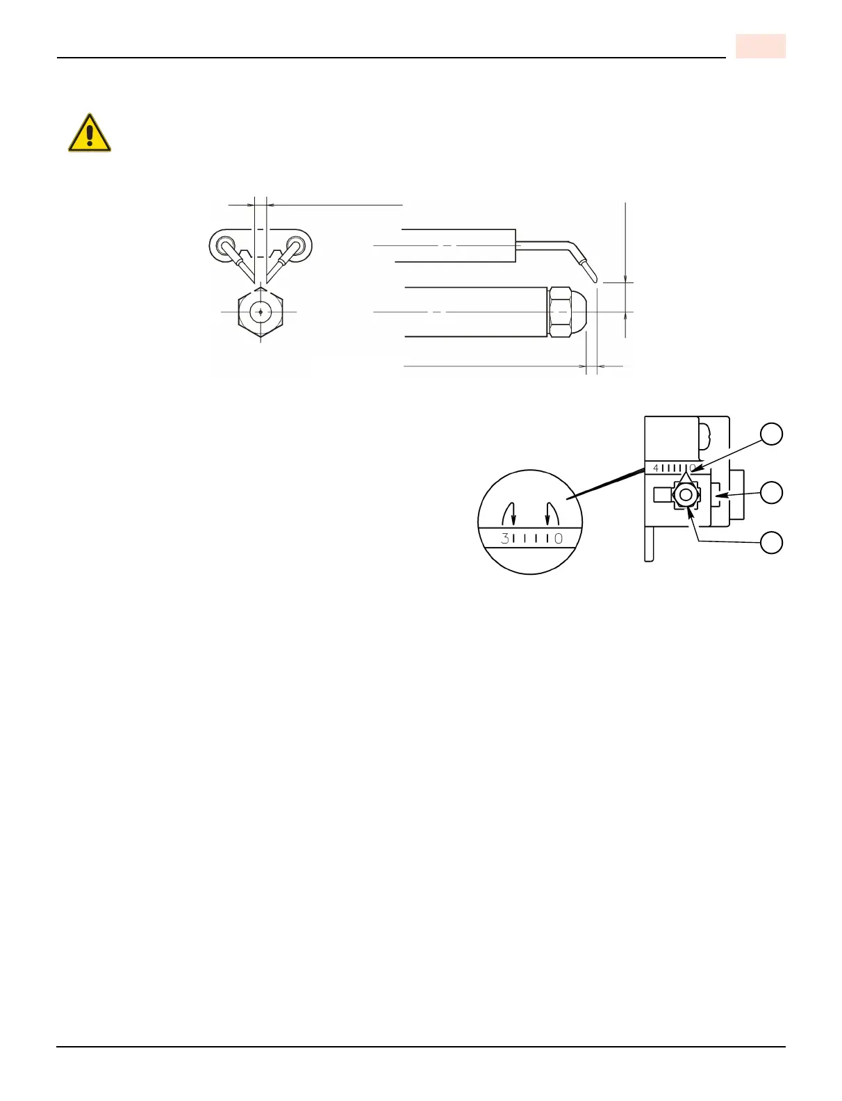
ELECTRODE SETTING
TURBULATOR SETTING
A) Loosen NUT (1), and then turn SCREW (2) until the IN-
DEX MARKER (3) is aligned with the correct index num-
ber as per the Burner Setup charts, or OEM
specifications given with the appliance.
B) Re-tighten the RETAINING NUT (1).
NOTE:
OEM specifications take priority over retrofit specifica-
tions shown in this manual.
MODEL F3:
Zero and three are scale indicators only. From left to
right the first line is 3 and the last line 0.
MODEL F5:
Same as above, except scale indicators are 0 and 4.
IMPORTANT: These dimensions must be observed and verified.
WARNING
5 / 32” (4 mm)
13 / 64” (5 mm)
D6003
5 / 64” ÷ 7 / 64” (2 ÷ 2,5 mm)
3
2
1
D7520