2903223
13
GB
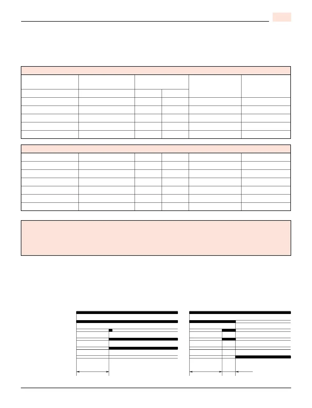
BURNER ADJUSTMENT TABLE
NON-RETROFIT APPLICATIONS
If this burner is being installed in a packaged unit (i.e. Burner comes with a boiler or furnace), follow the instal-
lation and set-up instructions supplied with the heating appliance, as settings will differ from those shown in
this manual.
COMBUSTION CHAMBER
Follow the instructions furnished by the boiler/furnace manufacturer. Size retrofit application according to the appropri-
ate installation codes (e.g. CSA B139 or NFPA #31).
BURNER START-UP CYCLE
MODEL F3 BURNER
Actual Firing
Rate 5% ±
Nozzle
Size
Pump
Pressure
Turbulator
Setting
Air Damper
Setting
US GPH GPH PSI bar
0.50 .40 x 60º/80º 160 11.0 0.0 2.3
0.60 .50 x 60º/80º 150 10.4 0.5 2.7
0.75 .60 x 60º/80º 150 10.4 1.5 3.4
0.80 .65 x 60º/80º 150 10.4 2.0 3.6
0.95 .75 x 60º/80º 160 11.0 3.0 4.3
MODEL F5 BURNER
0.75 .60 x 60/ 80º 145 10 0.0 2.25
0.85 .65 x 60/ 80º 145 10 0.5 2.5
1.00 .85 x 60/ 80º 145 10 1.0 2.75
1.10 1.00 X 60/ 80° 145 10 2.0 3.0
1.25 1.10 x 60/ 80º 145 10 2.5 3.5
1.50 1.25 x 60/ 80º 145 10 3.0 4.25
1.65 1.35 X 60/ 80° 145 10 4.0 6.0
NOTE:
The above set up charts are a starting point only.
The burner and appliance must be properly set up using proper combustion testing equipment.
Any approved oil burner nozzle type, angle and manufacturer maybe used, as long as input is corresponding
the correct BTU/hr. or US gph input rating of the appliance.
Normal Lock-out, due to light-failure
Thermostat
Motor
Ignition transformer
Valve
Flame
Lock-out lamp
~ 12 s ~ 12 s ~ 5 s
D5229