1. BURNER DESCRIPTION. . . . . . . . . . . . . . . . . . . . . . . . . . . . . . . . . . . . . . . . . . . . . . . . . . . . . . . . . . . . . . . . 2
1.1 Standard equipment . . . . . . . . . . . . . . . . . . . . . . . . . . . . . . . . . . . . . . . . . . . . . . . . . . . . . . . . . . . . . . . . . . . . 2
2. TECHNICAL DATA. . . . . . . . . . . . . . . . . . . . . . . . . . . . . . . . . . . . . . . . . . . . . . . . . . . . . . . . . . . . . . . . . . . . . 3
2.1 Dimensions . . . . . . . . . . . . . . . . . . . . . . . . . . . . . . . . . . . . . . . . . . . . . . . . . . . . . . . . . . . . . . . . . . . . . . . . . . . 3
2.2 Firing rate . . . . . . . . . . . . . . . . . . . . . . . . . . . . . . . . . . . . . . . . . . . . . . . . . . . . . . . . . . . . . . . . . . . . . . . . . . . . 3
3. HYDRAULIC SYSTEMS. . . . . . . . . . . . . . . . . . . . . . . . . . . . . . . . . . . . . . . . . . . . . . . . . . . . . . . . . . . . . . . . . 4
4. ELECTRICAL SYSTEM . . . . . . . . . . . . . . . . . . . . . . . . . . . . . . . . . . . . . . . . . . . . . . . . . . . . . . . . . . . . . . . . . 5
4.1 Electrical system factory-set . . . . . . . . . . . . . . . . . . . . . . . . . . . . . . . . . . . . . . . . . . . . . . . . . . . . . . . . . . . . . . 5
4.2 Electrical connection to the terminal strip . . . . . . . . . . . . . . . . . . . . . . . . . . . . . . . . . . . . . . . . . . . . . . . . . . . . 5
5. BURNER ADJUSTMENT. . . . . . . . . . . . . . . . . . . . . . . . . . . . . . . . . . . . . . . . . . . . . . . . . . . . . . . . . . . . . . . . 6
5.1 Combustion head adjustment . . . . . . . . . . . . . . . . . . . . . . . . . . . . . . . . . . . . . . . . . . . . . . . . . . . . . . . . . . . . . 6
5.2 Air damper adjustment . . . . . . . . . . . . . . . . . . . . . . . . . . . . . . . . . . . . . . . . . . . . . . . . . . . . . . . . . . . . . . . . . . 7
5.3 Positioning of electrodes. . . . . . . . . . . . . . . . . . . . . . . . . . . . . . . . . . . . . . . . . . . . . . . . . . . . . . . . . . . . . . . . . 7
6. PRIMING THE PUMP. . . . . . . . . . . . . . . . . . . . . . . . . . . . . . . . . . . . . . . . . . . . . . . . . . . . . . . . . . . . . . . . . . . 7
7. BURNER START-UP CYCLE. . . . . . . . . . . . . . . . . . . . . . . . . . . . . . . . . . . . . . . . . . . . . . . . . . . . . . . . . . . . . 7
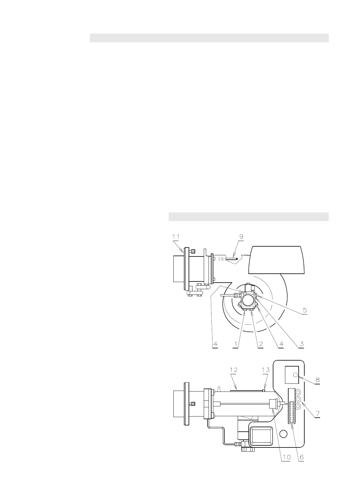
1. BURNER DESCRIPTION
1 - Suction line fitting
2 - Return line fitting
3 - Suction gauge fixing point (G 1/8)
4 - Pressure gauge fixing point (G 1/8)
5 - Pump pressure adjuster
6 - Wiring terminal block
7 - Fairleads
8 - Control box reset-button with signal of
lock-out
9 - Combustion head control shaft
10 - Photoresistance
11 - Flange with thermal insulation screen
12 - Air damper
13 - Screw for fixing air damper and as point of
reference for its adjustment
1.1 STANDARD EQUIPMENT
Flexibles oil-lines with nipples and gaskets . N° 2
Flange with thermal insulation screen. . . N° 1
Screws and nuts for flange . . . . . . . . . . . N° 4
Nozzles . . . . . . . . . . . . . . . . . . . . . . . . . . N° 2
Screws with two nuts for flange. . . . . . . . N° 1
Hinge. . . . . . . . . . . . . . . . . . . . . . . . . . . . N° 1
 Loading...