Electrical connections must
be made by qualified and
skilled personnel in
conformity with the local
regulations in force.
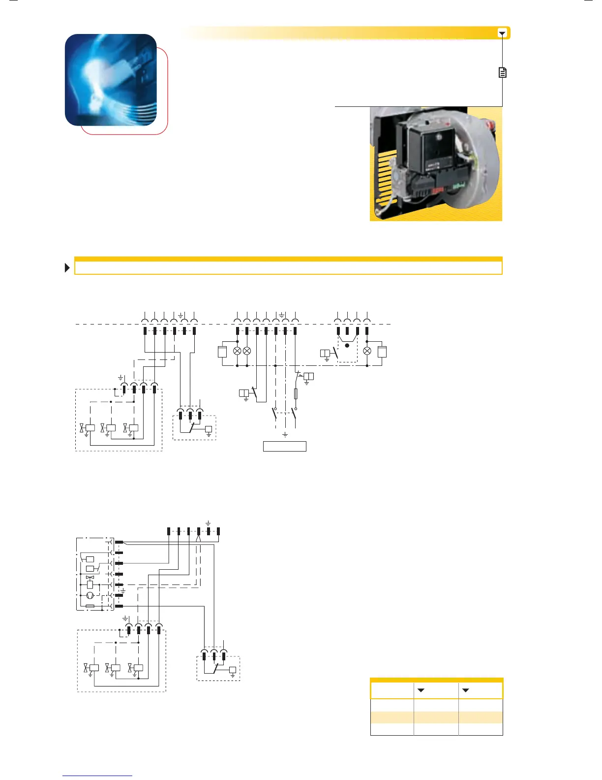
The 7-pole socket, the 4-pole
socket (for connecting the 2nd stage thermostat and the hour
meter) and the 6-pole socket (for connection to the gas train)
are connected to the equipement and fixed into the burner.
The 7 and 4-pin plugs are supplied for connection to the boiler.
WIRING DIAGRAMS
Appliance fitted with 7-pole, 6-pole
and 4-pole sockets
The following table shows the
supply lead sections and types
of fuse to be used.
TWO STAGE OPERATION
(*) Connect 2nd stage thermostat between
clamps T6 and T8 removing the bridge.
Electrical wiring with gas leak
control device (DUNGS VPS 504)
P
PG
V11V10
V12
P
TS
FUSE
(*)
P
PG
V10V11
VPS
B5
N
L1
T6
T8
T7
V12
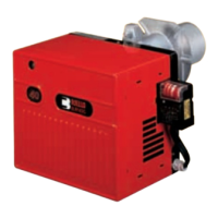
GS10D - GS20D
XP4 - 4 pole socket
XP6 - 6 pole socket
XP7 - 7 pole socket
X4 - 4 pin plug
X6 - 6 pin plug
X7 - 7 pin plug
B4 - 1
st
stage working signal
B5 - 2
nd
stage working signal
h1 - 1
st
stage hour counter
h2 - 2
nd
stage hour counter
PG - Minimum gas pressure switch
S3 - Remote lock-out signal
(230V - 0,5A max.)
TL - Limit thermostat
TR - 2
nd
stage thermostat
TS - Safety thermostat
V10 - Safety valve
V11 - 1
st
stage valve
V12 - 2
nd
stage valve
X6
321
321
X7
XP7
S3
N L
B4
B5
X4
XP4
X6
321
321
32 N Ph1
ϑ
B4 S3 T2 N
L1
T1
TL
P
ϑ
h1
~
230V 50Hz
XP6
32 N Ph1
GS10D
Model
A
mm
2
F
L
230V
T6
1
F = Fuse L = Lead section
GS20D
230V
T6
1
h1
B5T8 T7 T6
TR
P
ϑ
10