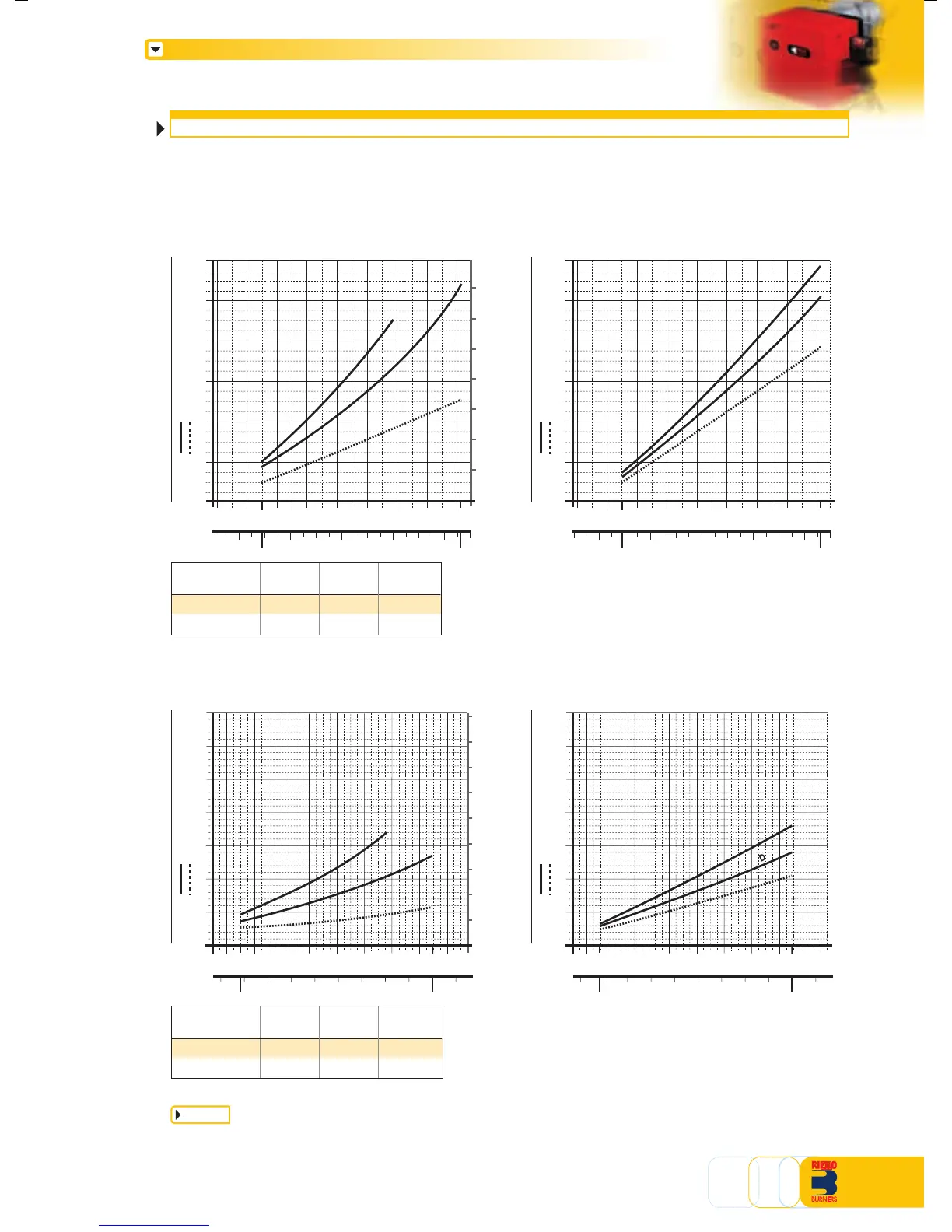
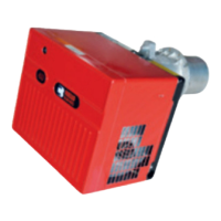
PRESSURE DROP DIAGRAM
The diagrams indicate the minimum pressure drop of the burners with the various gas trains that
can be combined with them; the value thus calculated represents the minimum required input
pressure to the gas train.
NATURAL GAS LPG
GS10D
0
GS10D
NATURAL GAS LPG
GS20D GS20D
For pressure levels different from those indicated above, please
contact Riello Burners Technical Office.
In LPG plants, Multibloc gas trains do not operate below 0
°
C.
They are only suitable for gaseous LPG (liquid hydrocarbons destroy
the seal materials).
note
Gas train
MBZRDLE 407
MBZRDLE 410
Code
3970537
3970534
Plug and
socket
•
•
Output
kW
≤ 180 (*)
(*) With natural gas.
Gas train
MBZRDLE 405
MBZRDLE 407
Code
3970084
3970537
Plug and
socket
•
•
Output
kW
≤ 80 (*)
-
(*) With natural gas.
ΔP
combustion head + gas train
combustion head
Pressure loss
kcal/h X 1000
kW
0
29
mbar
M
B
Z
R
D
L
E
4
0
7
G20 G25
kW
106
10 50 70 90 110
30 40 50 60 70 80 91,22510
ΔP
combustion head + gas train
combustion head
Pressure loss
mbar
MBZRDLE 405
MBZRDLE 410
kW120
0
100 200
5
10
15
20
25
30
35
140 180160
220
10080 120 140 1891606040
58
40
kcal/h x 1000
0
5
15
25
30
35
20
10
40
45
G20 G25
80
MBZRDLE 4
07
50
ΔP
combustion head + gas train
combustion head
Pressure loss
kcal/h X 1000
kW
0
29
mbar
M
B
Z
R
DL
E
4
0
7
LPG
kW
106
10 50 70 90 110
30 40 50 60 70 80 91,22510
MBZRDLE 405
4
2
6
10
8
ΔP
combustion head + gas train
combustion head
Pressure loss
mbar
MBZRDLE 410
kW120
0
100 200
5
10
15
20
25
30
35
140 180160
220
10080 120 140 1891606040
58
40
kcal/h x 1000
LPG
80
MBZRDLE 407
50
2
8
10
6
4
2
6
10
8
4
12
12
14
12
5