2754
1
GB
INDEX
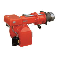
1. BURNER DESCRIPTION
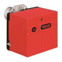
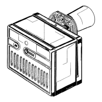
Gas burner with one stage working.
1.1 BURNER EQUIPMENT
Insulating gasket . . . . . . . . . . . . . No. 1 Screws and nuts for flange to be fixed to boiler . . No. 4
Cable grommet . . . . . . . . . . . . . . No. 1 Screw for fixing the cover . . . . . . . . . . . . . . . . . . . No. 1
Hinge . . . . . . . . . . . . . . . . . . . . . . No. 1 Pipe fitting for gas train . . . . . . . . . . . . . . . . . . . . No. 1
1. BURNER DESCRIPTION . . . . . . . . . . . 1
1.1 Burner equipment . . . . . . . . . . . . . . . . . 1
2. TECHNICAL DATA . . . . . . . . . . . . . . . . 2
2.1 Technical data . . . . . . . . . . . . . . . . . . . . 2
2.2 Overall dimensions . . . . . . . . . . . . . . . . 2
2.3 Working field . . . . . . . . . . . . . . . . . . . . . 2
2.4 Correlation between gas pressure and
burner output . . . . . . . . . . . . . . . . . . . . 3
3. INSTALLATION . . . . . . . . . . . . . . . . . . 3
3.1 Boiler fixing . . . . . . . . . . . . . . . . . . . . . . 3
3.2 Probe-electrode positioning. . . . . . . . . . 4
3.3 Gas feeding line . . . . . . . . . . . . . . . . . . 4
3.4 Electrical wiring. . . . . . . . . . . . . . . . . . . 5
3.5 Fixing the electrical wiring . . . . . . . . . . . 6
4. WORKING . . . . . . . . . . . . . . . . . . . . . . . 6
4.1 Combustion head setting . . . . . . . . . . . . 6
4.2 Air damper setting . . . . . . . . . . . . . . . . . 6
4.3 Combustion check . . . . . . . . . . . . . . . . . 7
4.4 Burner start-up cycle . . . . . . . . . . . . . . . 7
4.5 Start-up cycle diagnostics. . . . . . . . . . . . 7
4.6 Resetting the control box and using
diagnostics . . . . . . . . . . . . . . . . . . . . . . . 8
5. MAINTENANCE. . . . . . . . . . . . . . . . . . . 9
6. FAULTS / SOLUTIONS . . . . . . . . . . . . . 10
NOTES:
– Gas train can be installed on the right or on the left of the burner.
– The cable grommet (4) and the screw for fixing the cover (5) supplied with the burner, must be fitted to
the same side of the gas train.
1 – Air-damper
2 – Screws for fixing the air-damper
3 – Cable clamps
4 – Cable grommet
5 – Screw for fixing the cover
6 – Air pressure switch
7 – Terminal board
8 – Control box
9 – Reset button with lock-out lamp
Fig. 1
2
1
2
D4178
5 4 3
9
8
7
6
❱
The burner meets protection level of IP X0D (IP 40), EN 60529.
❱
The burner is approved for intermittent operation as per Directive EN 676.