20049406
8
Installation
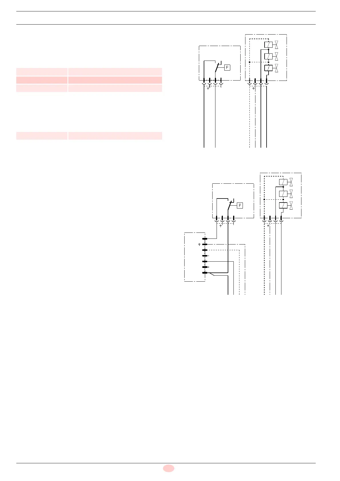
4.6.1 Connections for burners with terminal board
The gas trains shown in Tab. D are prepared in the factory to be
connected in accordance with the electrical diagram shown in
Fig. 5.
Tab. D
The gas train shown in Tab. E is prepared in the factory to be con-
nected in accordance with the electrical diagram shown in Fig. 6.
Tab. E
Key
PG Min gas pressure switch
V Valve group V1 - V2 - VS
VPS Valve leak detection control device
BN Brown
BU Blue
BK Black
YE Yellow
Code Model
3970152 MB 412/2 - RT 20
3970183 MB 415/2 - RT 20
3970184 MB 420/2 - RT 20
Code Model
3970185 MB 420/2 CT RT 20
BU
YE
BK
BN
PG
V1
V2
3
21
1
23
V
VS
P
P
V2
V1
N
T8
T7
T6
B5
N
L1
2
31
T6
T8
N
V1
BU
YE
BK
BN
V2
VPS
1
23
V1
V2
V
VS
BU
YE
BN
BK
PG
 Loading...