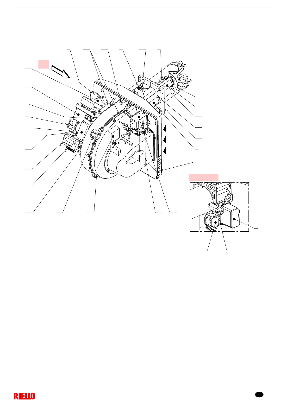
1 Combustion head
2 Ignition electrode
3 Screw for combustion head adjustment
4 Pipe coupling
5 Gas servomotor
6 Plug-socket on ionisation probe cable
7Motor relay
8 Operation on/off switch (“1-0”)
9 Terminal board for electrical wiring
10 Operator panel with LCD display
11 Control box for checking flame and air/
fuel ratio
12 Clean contact relay
13 Filter to protect against radio distur-
bance
14 Flame inspection window
15 Ignition transformer
16 Cable grommets for electrical wiring
(to be carried out by the installer)
17 Air servomotor
18 Air pressure switch
(differential type)
19 Guides for opening the burner and
inspecting the combustion head
20 Gas pressure test point and head fix-
ing screw
21 Air pressure socket
22 Flame sensor probe
23 Air damper
24 Fan air inlet
25 Screw to secure fan to the pipe cou-
pling
26 Gas input pipe
27 Gas regulator
28 Boiler fixing flange
29 Flame stability disc
30 Bracket for application of output regu-
lator RWF40
Fig. 5
seen from A
A
D8043
The burner is supplied complete with:
Gas train flange
Flange gasket
4 screws to fix the flange: M8 x 25
4 screws to fix the burner flange to the boiler:
M8 x 25
Thermal insulation screen
N° 3 plugs for electrical wiring
Instruction manual
Spare parts list