17
GB
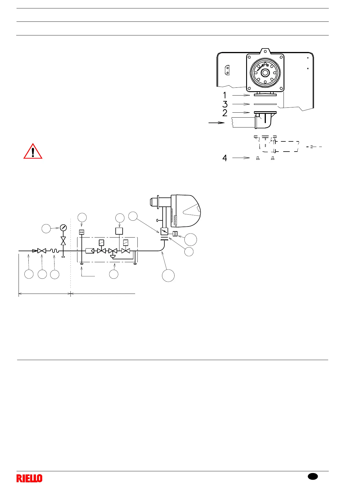
4.7 Assembly of the gas train
The gas train is type-approved according to standard EN 676 and is sup-
plied separately from the burner, with the code indicated in Appendix B.
The gas train can enter the burner from the right or left side, depending
on which is the most convenient, see Fig. 18.
The gas train must be connected to the gas attachment 1) (Fig. 18) with
the flange 2), the gasket 3) and the screws 4) supplied with the burner.
The gas solenoids must be as close as possible to the burner, to ensure
that the gas reaches the combustion head within the safety time of 3s.
Ensure that the maximum pressure to the burner is within the calibration
range of the pressure adjuster.
The losses of load along the gas supply line are indicated in Appendix C.
See the accompanying instructions for the adjustment of
the gas train.
1 - Gas input pipe
2 - Manual valve
3 - Vibration damping joint
4 - Pressure gauge with pushbutton cock
5 - Multibloc, including:
- filter (replaceable)
- working valve
- pressure adjuster
6 - Minimum gas pressure switch
7 - Valve leak detection control device.
In accordance with the standard EN 676,
leak detection is compulsory for burners
with maximum outputs of more than
1200 kW.
8-Gasket
9 - Gas adjustment butterfly valve
10 - Maximum gas pressure switch (accessory)
11 - Gas train/burner adaptor
P1 - Pressure at combustion head
P2 - Upstream pressure of valves/adjuster
L - Gas train supplied separately with the code
indicated in Appendix B.
L1 - The responsibility of the installer
Fig. 19
Installation
4