17
20144609
Installation
5.6 Access to head internal part
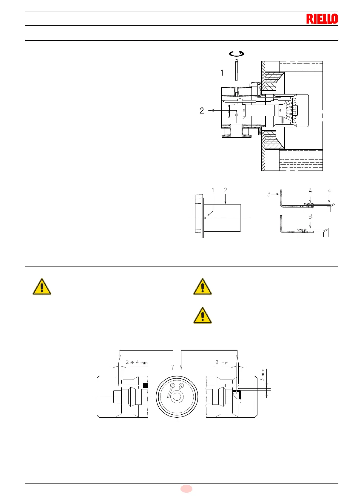
In order to reach inside the combustion head (Fig. 11) proceed as
follows:
remove the screw 1) and take out the internal part 2).
5.6.1 Combustion head pre-calibration
For the RS 130 model, check, at this point, whether the maximum
output of the burner in the 2nd stage is within area A or in area B
of the firing rate. See “Firing rates” on page 10.
– If it is in area A, no intervention is required.
– However, if it is in area B:
Unscrew the screws 1)(Fig. 12) and remove the blast tube
2).
Move the fixing point of the rod 3)(Fig. 12) from position A to
position B, thereby moving the shutter 4) backwards.
Put back the blast tube 2)(Fig. 12) and the screws 1).
Once this operation has been carried out, fix the flange 9)(Fig. 10
on page 16) to the boiler plate, interposing the insulating gasket
7)(Fig. 10 on page 16) supplied. Use the 4 screws, also supplied
with the unit, after protecting the thread with anti-locking product.
5.7 Positioning the probe - electrode
If the probe or electrode is not correctly positioned, you must:
remove the screw 1)(Fig. 11);
take out the inner part 2)(Fig. 11) of the head, and then cali-
brate them.
Before securing the burner to the boiler, check
(through the opening of the blast tube) that the
probe and electrode are correctly positioned, as in
Fig. 13.
Do not rotate the probe: leave it as in Fig. 13 since
if it is located too close to the ignition electrode,
the control box amplifier may be damaged.
Respect the dimensions shown in Fig. 13.
PROBE ELECTRODE
Fig. 13
D613


 To Next Page