27
20144609
Start-up, calibration and operation of the burner
6.6 Pressure switch adjustment
6.6.1 Air pressure switch
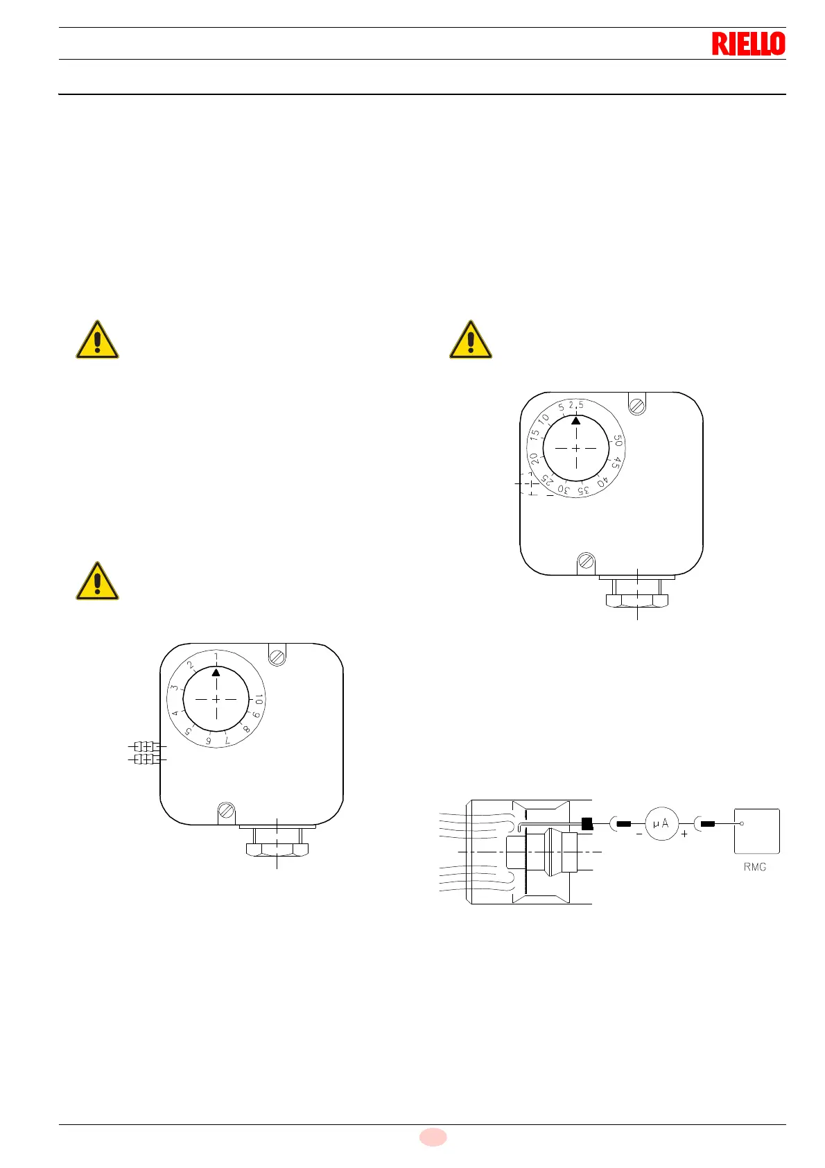
Adjust the air pressure switch after performing all other burner
adjustments with the air pressure switch set to the start of the
scale (Fig. 27).
With the burner operating in the 1st stage, increase adjustment
pressure by slowly turning the relative knob clockwise until the
burner locks out.
Then turn the knob anti-clockwise by about 20% of the set point
and repeat burner starting to ensure it is correct.
If the burner locks out again, turn the knob anti-clockwise a little
bit more.
The incorporated air pressure switch can work in a 'differential'
mode if connected with two pipes. If a negative pressure in the
combustion chamber during pre-purging prevents the air pres-
sure switch from switching. Switching may be obtained by fitting
a second pipe between the air pressure switch and the suction in-
let of the fan. In such a manner the air pressure switch operates
as differential pressure switch.
6.6.2 Minimum gas pressure switch
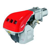
Adjust the minimum gas pressure switch after performing all the
other burner adjustments with the pressure switch set to the start
of the scale (Fig. 28).
With the burner operating in the 2nd stage, increase adjustment
pressure by slowly turning the relative knob clockwise until the
burner stops.
Then turn the knob anticlockwise by 0.2 kPa (2 mbar) and repeat
burner start-up to ensure it is uniform.
If the burner locks out again, turn the knob anticlockwise again by
0.1 kPa (1 mbar).
6.6.3 Flame presence check
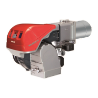
The burner is fitted with an ionisation system to check that a
flame is present. The minimum current for control box operation
is 5 A. The burner provides a much higher current, so controls
are not normally required. However, if it is necessary to measure
the ionisation current, disconnect the plug-socket 8)(Fig. 4 on
page 12) on the ionisation probe cable and insert a direct current
micro-ammeter for 100 A base scale continuous current. Care-
fully check polarities!
In conformity with the standard, the air pressure
switch must prevent the CO in the flue gases from
exceeding 1% (10,000 ppm).
To check this, insert a combustion analyser into
the chimney, slowly close the fan suction inlet (for
example with cardboard) and check that the burn-
er locks out, before the CO in the fumes exceeds
1%.
The use of the air pressure switch with differential
operation is allowed only in industrial applications
and where rules enable the air pressure switch to
control only fan operation without any reference to
CO limit.
1 kPa = 10 mbar


 To Next Page