20144609
32
Maintenance
Boiler
Clean the boiler as indicated in its accompanying instructions in
order to maintain all the original combustion characteristics in-
tact, especially: the flue gas temperature and combustion cham-
ber pressure.
Gas leaks
Make sure that there are no gas leaks on the pipe between the
gas meter and the burner.
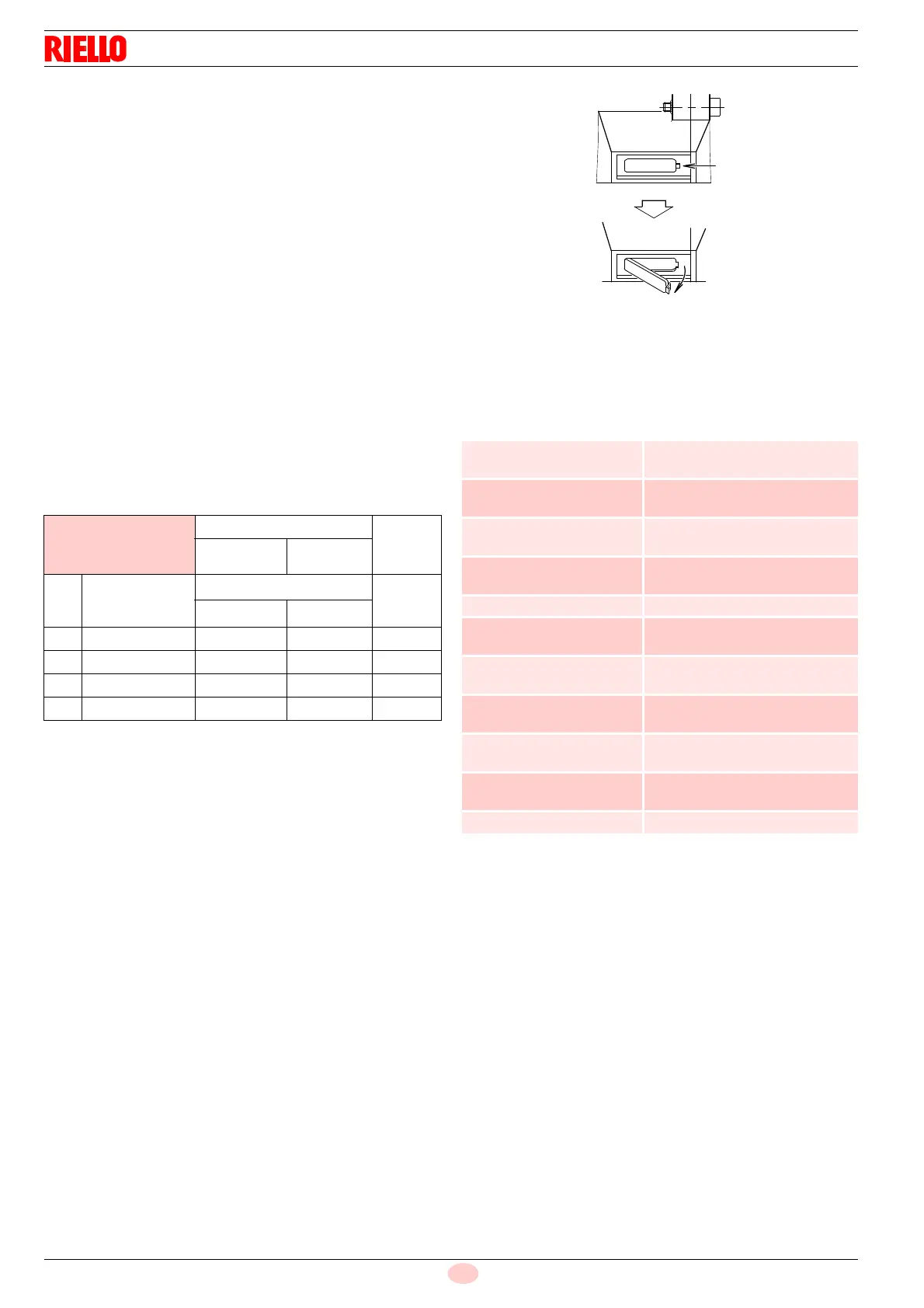
Flame inspection window
Clean the glass of the flame inspection window.
7.2.4 Combustion control (gas)
The optimum calibration of the burner requires an analysis of the
flue gases.
Significant differences with respect to the previous measure-
ments indicate the points where more care should be exercised
during maintenance.
In case the combustion values found at the beginning of the inter-
vention do not respect the standards in force or, in any case, do
not correspond to a proper combustion, contact the Technical As-
sistance Centre in order to carry out the necessary adjustments.
Tab. K
CO
2
It is advisable to adjust the burner with a CO
2
not greater than
about 10% (gas con Ncv 8600 kcal/m
3
). In this way it is avoided
that a small decalibration (for example a variation in the tension)
could cause a combustion with an air defect and with the subse-
quent formation of CO.
CO
It should not exceed 100 mg/kWh.
7.2.5 Safety components
The safety components should be replaced at the end of their life
cycle indicated in Tab. L. The specified life cycles do not refer to
the warranty terms indicated in the delivery or payment condi-
tions.
Tab. L
EN 676
Air excess
CO
Max. output
1.2
Max. output
1.3
GAS
Theoretical
max CO
2
0 % O
2
CO
2
% Calibration
mg/kWh
= 1.2
= 1.3
G 20 11.7 9.7 9 1000
G 25 11.5 9.5 8.8 1000
G 30 14.0 11.6 10.7 1000
G 31 13.7 11.4 10.5 1000
Safety component Life cycle
Flame control
10 years or 250,000
operation cycles
Flame sensor
10 years or 250,000
operation cycles
Gas valves (solenoid)
10 years or 250,000
operation cycles
Pressure switches
10 years or 250,000
operation cycles
Pressure adjuster 15 years
Servomotor
(electronic cam) (if present)
10 years or 250,000
operation cycles
Oil valve (solenoid)
(if present)
10 years or 250,000
operation cycles
Oil regulator (if present)
10 years or 250,000
operation cycles
Oil pipes/ couplings
(metallic) (if present)
10 years
Hoses (if present)
5 years or 30,000
pressurised cycles
Fan impeller 10 years or 500,000 start-ups


 To Next Page