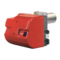
21
20144609
Installation
Column 1
Combustion head pressure drop.
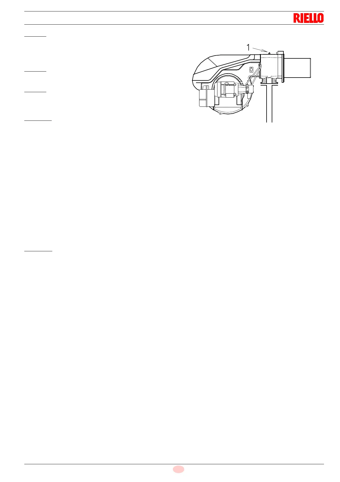
Gas pressure measured at the test point 1)(Fig. 21), with:
• combustion chamber at 0 mbar;
• burner working at maximum output
Column 2
Pressure loss at gas butterfly valve 2)(Fig. 21) with maximum
opening: 90°.
Column 3
Pressure loss of gas train 3)(Fig. 21) includes: adjustment valve
VR, safety valve VS (both fully open), pressure adjuster R, filter
F.
To calculate the approximate output at which the burner operates
in the 2nd stage:
– subtract the combustion chamber pressure from the gas
pressure measured at test point 1)(Fig. 21).
– Find, in Tab. G related to the burner concerned, the pressure
value closest to the result of the subtraction.
– Read the corresponding output on the left.
Example - RS 100:
2nd stage operation
Natural gas G 20 NCV 10 kWh/Nm
3
Gas ring nut 2)(Fig. 14 on page 18) adjusted as in the diagram
(Fig. 15 on page 18).
Gas pressure at test point 1)(Fig. 21) = 8.0 mbar
Pressure in combustion chamber = 3.0 mbar
8.0 - 3.0 = 5.0 mbar
A pressure of 5 mbar, column 1, corresponds in the table RS 100
to an output in the 2nd stage of 825 kW.
This value serves as a rough guide; the effective output must be
measured at the gas meter.
To calculate
the required gas pressure at test point 1)(Fig. 21),
set the maximum modulating output required from the burner op-
eration:
– find the nearest output value in Tab. G for the burner in ques-
tion.
– read, on the right (column 1), the pressure at the test point 1)
(Fig. 21).
– Add this value to the estimated pressure in combustion
chamber.
Example - RS 100:
Desired output in 2nd stage: 825 kW
Natural gas G 20 NCV 10 kWh/Nm3
Gas ring nut 2)(Fig. 14 on page 18) adjusted as in the diagram
(Fig. 15 on page 18).
Gas pressure at an output of 825 kW = 5.0 mbar
Pressure in combustion chamber = 3.0 mbar
5.0 + 3.0 = 8.0 mbar
pressure required at test point 1)(Fig. 21).


 To Next Page