RIGOL Chapter 2 Constant Voltage Tests
DP800 Performance Verification Manual
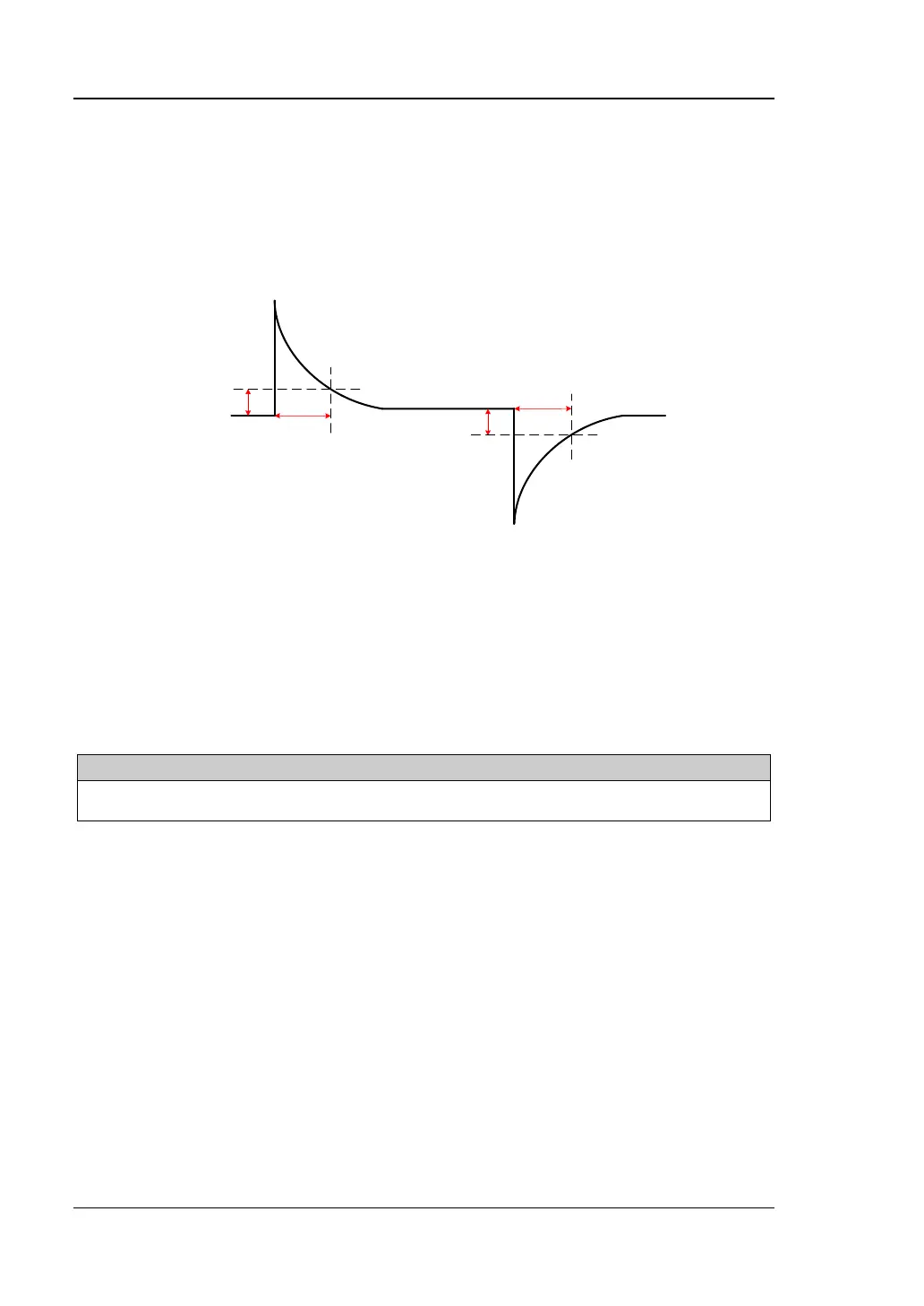
Transient Response Time
Transient response time refers to the time required for the output voltage of the
power supply to recover to within 15mV following a transient variation in the load
current (50% transient variation, namely the output current changes from full load to
half load or vice versa). As shown in Figure 2-4, t is the transient response time.
Figure 2-4 Transient Response Time
DP831A is taken as an example to test the transient response time of DP800 series in
the following section.
Note: During the actual test, please select the corresponding test record form
according to the model of the DP800 power supply under test to set the
corresponding parameters, record and calculate the corresponding specifications.
Specification:
Transient Response Time
Less than 50μs for output voltage to recover to within 15 mV following a change in output
current from full load to half load or vice versa.
Test Procedures:
1. Turn off DP800. Connect DP800, AC power supply, electronic load and
oscilloscope according to Figure 2-1. Both the electronic load and oscilloscope
are connected with the channel output terminals of DP800; please refer to “Test
Precautions” for the connection method. Here, CH1 is taken as an example
and the connection method is also applicable to CH2 and CH3
2. Turn on the AC power supply; set its voltage to 230V and frequency to 50Hz.
Note: The voltage setting of the AC power supply in this step should be in
accordance with the value selected by the voltage selector at the rear panel of
DP800.
 Loading...