Chapter 2 Performance Verification Test RIGOL
DS6000 Performance Verification Guide
DC Gain Accuracy Test
Specification
DC Gain Accuracy
Specification ±2% × Full Scale
[1]
Note
[1]
: Full Scale = 8 × Current Vertical Scale.
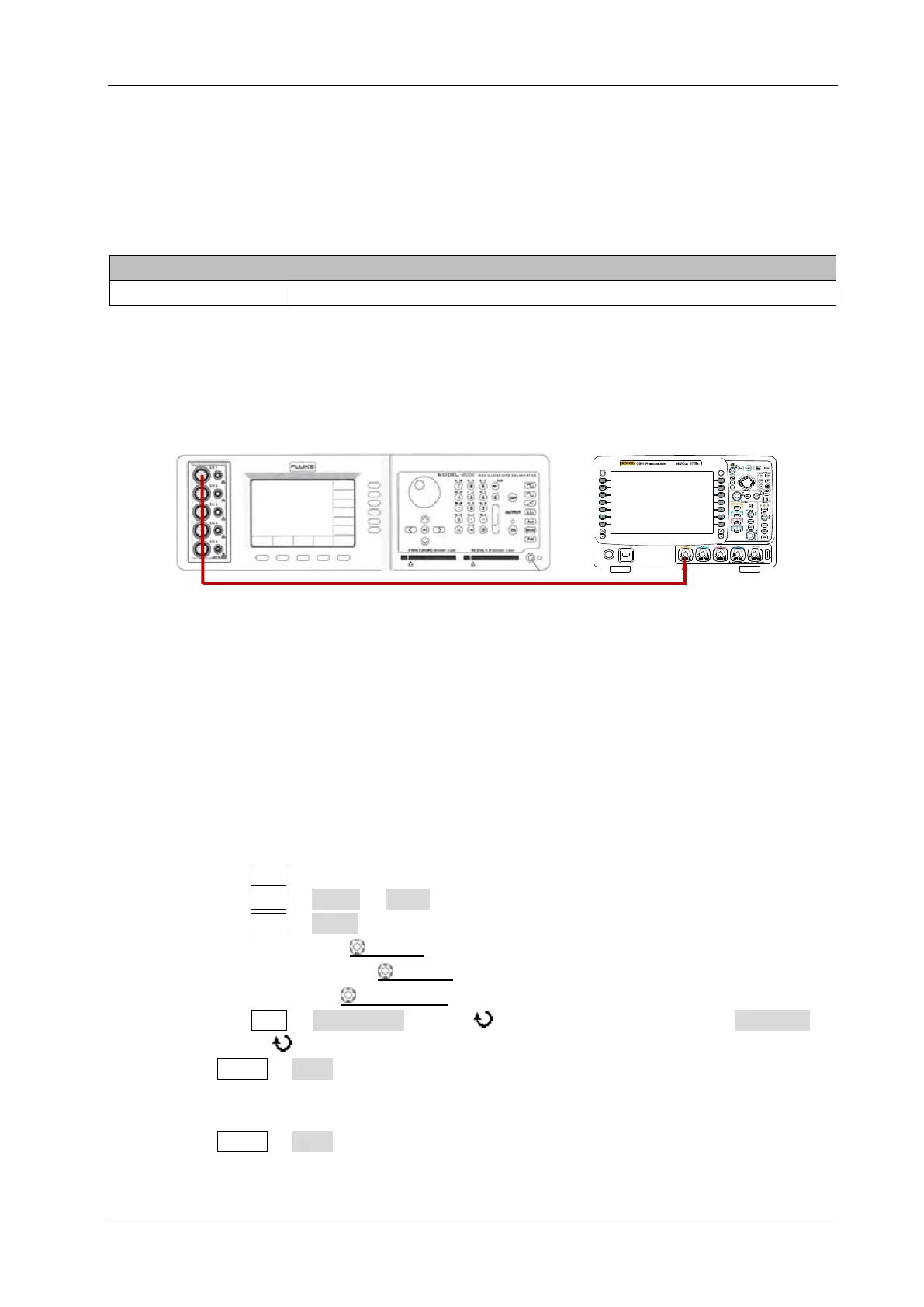
Test Connection Diagram
Figure 2-2 DC Gain Accuracy Test Connection Diagram
Test Procedures
1. DC gain accuracy test when the input impedance is 50 Ω
1) Connect the active signal terminal of Fluke 9500B to CH1 of the oscilloscope, as shown in
the figure above.
2) Enable Fluke 9500B and set its impedance to 50 Ω.
3) Output a DC signal with +6 mV
DC
voltage (Vout1) via Fluke 9500B.
4) Configure the oscilloscope:
a) Press CH1 in the vertical control area (VERTICAL) at the front panel to enable CH1.
b) Press CH1 Probe Ratio to set the probe attenuation ratio to “1X”.
c) Press CH1 Input to set the input impedance of CH1 to 50 Ω.
d) Rotate VERTICAL SCALE to set the vertical scale to 2 mV/div.
e) Rotate HORIZONTAL SCALE to set the horizontal time base to 2 ms.
f) Press VERTICAL POSITION to set the vertical position to 0.
g) Press ACQ Acquisition and use to select “Average”. Then, press Averages
and use to set the number of averages to 32.
5) Press MENU Vavg at the left side of the screen of the oscilloscope to enable the average
measurement function. Read and record Vavg1.
6) Adjust Fluke 9500B to make it output a DC signal with -6 mV
DC
voltage (Vout2).
7) Press MENU Vavg at the left side of the screen of the oscilloscope to enable the average
measurement function. Read and record Vavg2.
Fluke 9500B
DS6000
 Loading...


