RIGOL Chapter 2 Performance Verification Test
2-18 DS6000 Performance Verification Guide
Time Base Accuracy Test
Specification
Time Base Accuracy
[1]
Specification ≤ ±(4 ppm + Clock Drift
[2]
× Number of years that the instrument has
been used
[3]
)
Note
[1]
: Typical.
Note
[2]
: Clock drift is lower than or equal to ±2 ppm/year.
Note
[3]
: For the number of years that the instrument has been used, please calculate according to the date in the
verification certificate provided when the instrument leaves factory.
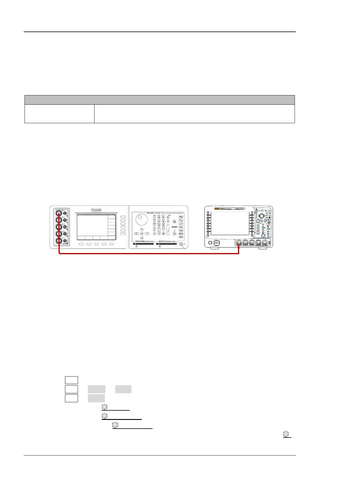
Test Connection Diagram
Figure 2-5 Time Base Accuracy Test Connection Diagram
Test Procedures
1. Connect the active signal terminal of Fluke 9500B to CH1 of the oscilloscope, as shown in the
figure above.
2. Enable Fluke 9500B and set its impedance to 50 Ω
3. Output a sine waveform with 10 MHz frequency and 1 Vpp amplitude via Fluke 9500B.
4. Configure the oscilloscope:
1) Press CH1 in the vertical control area (VERTICAL) at the front panel to enable CH1.
2) Press CH1 Probe Ratio to set the probe attenuation ratio to “1X”.
3) Press CH1 Input to set the input impedance to 50 Ω.
4) Rotate VERTICAL SCALE to set the vertical scale to 200 mV/div.
5) Rotate VERTICAL POSITION to set the vertical position to 0.
6) Rotate HORIZONTAL POSITION to set the horizontal position to 1 ms.
Tip: To quickly set the horizontal position to 1 ms, you can first rotate HORIZONTAL
Fluke 9500B
DS6000
 Loading...


