MerCruiser Thunderbolt V Ignition
Page 56
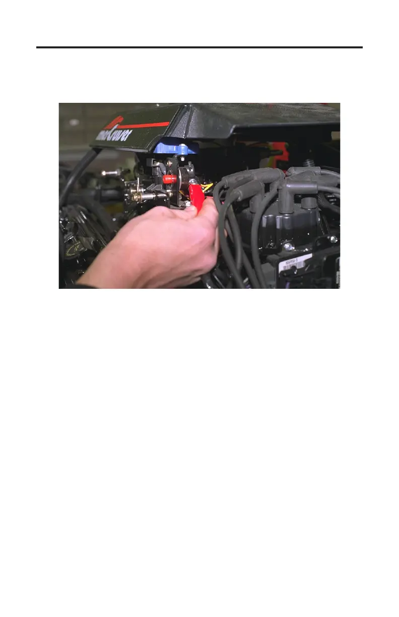
Figure 32 Circuit Breaker Terminal
5) With the engine’s ignition switch still in the OFF position, connect the
RED test lead to a +12 volt ignition power source. e engine’s circuit breaker
terminal, as shown in Figure 30, is a good connection for +12v power.
Connecting to 3rd Generation Thunderbolt V Modules
Connection of the scan tool to the 3rd generation underbolt V module re-
quires adapter #94020 attached to the tool. e adapter’s red and black battery
clips and square data connector will be used for this application. To properly
connect the scan tool to this module carefully proceed through the following
steps:
1) Before connecting the scan tool cables to the underbolt V module be sure
the engine’s ignition switch is in the OFF position.
2) Locate the 3rd generation underbolt V module mounted on the exhaust
elbow . Unplug the engine wiring harness from the module’s four pin data
connector. Plug the square connector of the underbolt V adapter into this
connector (see Figure 31 on the next page).
3) Connect the adapter’s BLACK test lead to a good ground location.
4) With the engine’s switch still in the OFF position, connect adapter’s RED test
lead to a +12 volt ignition power source. e engine circuit breaker terminal
is a good location for +12 volt power (as shown in Figure 30).