Agility 4 Quick Installation Guide
3
1. Introduction
This quick installation guide describes the main steps for installing the main panel and
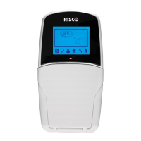
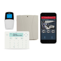
programming the Agility 4 using the 2-way wireless LCD or Panda keypad. The Agility 4 includes
multi-socket communication modules (IPC2, GSM 2G or GSM 3G) that provide multiple,
simultaneous communication channels for direct communication, and for communication via the
Cloud.
For installation procedures of system devices (detectors and accessories), refer to the Full Installer
Manual or the respective device’s instructions.
2. Installing the Main Panel
For optimal operation, the mounting location of the main panel should be:
• Centrally located among the wireless transmitting components
• In a location with good GSM reception
• Not visible from outside the protected premises, and not reachable by those for whom use is
unintended (such as small children)
• Near an uninterrupted 230V AC electrical outlet, phone outlet, network cable outlet as needed
• In a place where the alarm can be heard during Home/Stay (Partial) Arming mode
• Away from sources of direct heat, electrical disturbance and large metal objects, which may
hinder reception
To install the main panel:
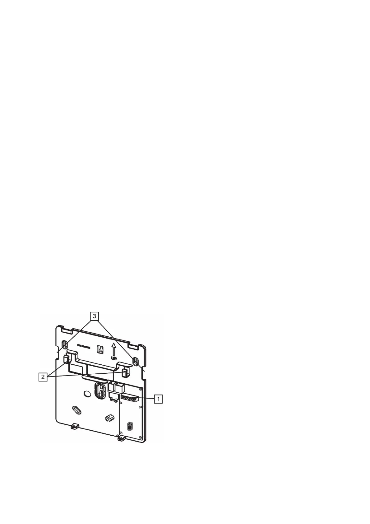
1. Disconnect the mounting bracket (back cover) from the main panel by releasing the two locking
screws, and then carefully disconnecting the flat ribbon cable from the printed circuit board
attached to the back bracket [1] while carefully leaving it connected to the main panel housing.
Mounting bracket (back cover)


 To Next Page