Do you have a question about the Risco LightSYS 2 Series and is the answer not in the manual?
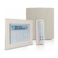
Basic introduction to the LightSYS2 hybrid security system.
Overview of the system's architecture, features, and capabilities.
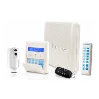
Details on the main panel, zone expansion, and wireless capabilities.
Explanation of the various channels for communication and reporting.
Principal communication channels including PSTN, IP, GSM/GPRS, and Long Range Radio.
Details on RISCO Cloud's application server and its features.
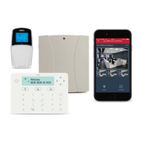
Explains end-user capabilities via smartphone app and web browser.
Recommended workflow for installing the LightSYS2 hardware.
Guidelines for selecting the optimal location for the main unit.
Procedure for preparing the wall and mounting the main enclosure.
Details on powering the system and installing the main board.
Explains the wiring diagram and connections for the main board.
Illustrates various zone connection configurations for the main unit or expanders.
Guidelines for powering PIRs, smoke detectors, and other 12V DC devices.
Steps for connecting the incoming telephone line for communication.
Procedures for installing GSM/GPRS and IP modules.
Configuration of plugs, DIP switches, and jumpers on the main unit.
Procedure for inserting and connecting the backup battery.
Details on connecting bus devices using the 4 bus terminals.
Instructions for setting device ID numbers using DIP switches.
Procedures for installing various expanders and accessories.
How to install LightSYS2 bus keypads.
Information on installing the 8-zone expander and its wiring.
Details on installing utility output expanders.
Steps for installing the wireless expander.
Installation of power supply modules.
Information on installing ProSound and Lumin 8 bus sounders.
Procedures for connecting addressable bus detectors.
How to connect a single zone expander.
Overview of the three methods for programming the LightSYS2 system.
Visual interface for operating and programming the system.
Steps to enter the installer programming mode.
Process for the system to detect and configure connected devices.
System's automatic bus scanning and device identification process.
Performing tests to ensure reliable connectivity of bus devices.
Steps for allocating and calibrating wireless devices.
Steps for programming bus detectors.
Procedures for safely exiting the installer programming mode.
How to reset the system to factory default settings.
Overview of navigating and using the installer menus.
Accessing system-wide configuration parameters.
Setting durations for actions like entry/exit delays and bell timeouts.
Parameters for controlling specific system operations.
Modifying displayed labels for system and partitions.
Setting sounds for system events.
System settings for compliance, languages, and defaults.
Retrieving automatic time updates.
Inserting service information.
Procedures for updating system firmware.
Configuring system zones.
Programming zone parameters.
Performing system tests.
Linking two zones for enhanced false alarm protection.
Defining protection against false alarms and alarm verification.
Configuring utility outputs based on system events.
Managing user codes, authority levels, and special codes.
Configuring system communication methods.
Defining voice message parameters for system announcements.
Adding, removing, or testing system accessories.
Manually configuring and modifying installed system devices.
User control over keypad sound and buzzer settings.
Configuring system events to follow defined destinations.
Accessing system status information.
Setting system time, date, and scheduler programs.
Viewing significant system events with date and time.
Performing system maintenance tasks.
Activating alarm sound from BUS sounders.
Activating strobes in connected BUS sounders.
Performing diagnostic tests on system components.
Key technical specifications for the main unit, including power, consumption, and dimensions.
Technical specifications for LCD and Touchscreen keypads.
Technical specifications for the 8-zone expander.
Specifications for 4-Relay and 8-Transistor output expanders.
Technical specifications for wireless expanders.
Technical specifications for ProSound and Lumin8 sirens.
List of available LightSYS2 keypads with their descriptions.
List of available zone expanders and their types.
List of available wireless expander models.
List of available power supply expansion modules.
List of output expansion modules.
List of voice module accessories.
List of available bus detectors with their descriptions.
Table showing wire facts, diameter, and resistance.
Recommended wire gauges for different distances.
Wire gauge recommendations for external sounder current.
A comprehensive list of pre-recorded voice messages and their corresponding numbers.
Tables listing Contact ID, SIA, and Report Category for various events.
Report codes for different alarm types and their status.
Report codes for arming and disarming events.
Report codes for detector zone events.
List of event messages and their descriptions for system logging.
A structured map of the installer programming menu options.
Navigation map for system settings like Timers, Controls, Communication, EN 50131, DD243 Prog, CP-01, and Device.
Map for configuring zone parameters, testing, cross zones, and alarm confirmation.
Map for configuring utility outputs based on system events.
Map for managing user codes, Grand Master, Installer, Sub Installer, and Code Length.
Map for configuring communication methods (PSTN, GSM, GPRS, Email, IP).
Map for audio settings like messages and local announcements.
Map for adding, removing, or testing system accessories.
Map for configuring system devices (Keypad, Keyfob, Sounder, etc.).
RISCO Group's declaration of compliance with EN standards.
Details on IP and GSM module compliance with EN50136 standards.
Guide on performing remote software upgrades via keypad or SMS.
Configuring communication parameters for the upgrade.
Specifying the server IP, port, and file name for the upgrade.
Initiating the remote upgrade process from the keypad.
Steps to check if the software upgrade was successful.
| Control Panel Type | Hybrid |
|---|---|
| Operating Temperature | -10°C to 55°C |
| Outputs | 4 |
| Communication | PSTN, GSM, IP |
| Wireless Frequency | 868MHz |
| Programming | Via keypad |
| Backup Battery | 12V, 7Ah |
| Remote Management | Yes |
| Humidity | Up to 93% non-condensing |