7
Right Terminal Description
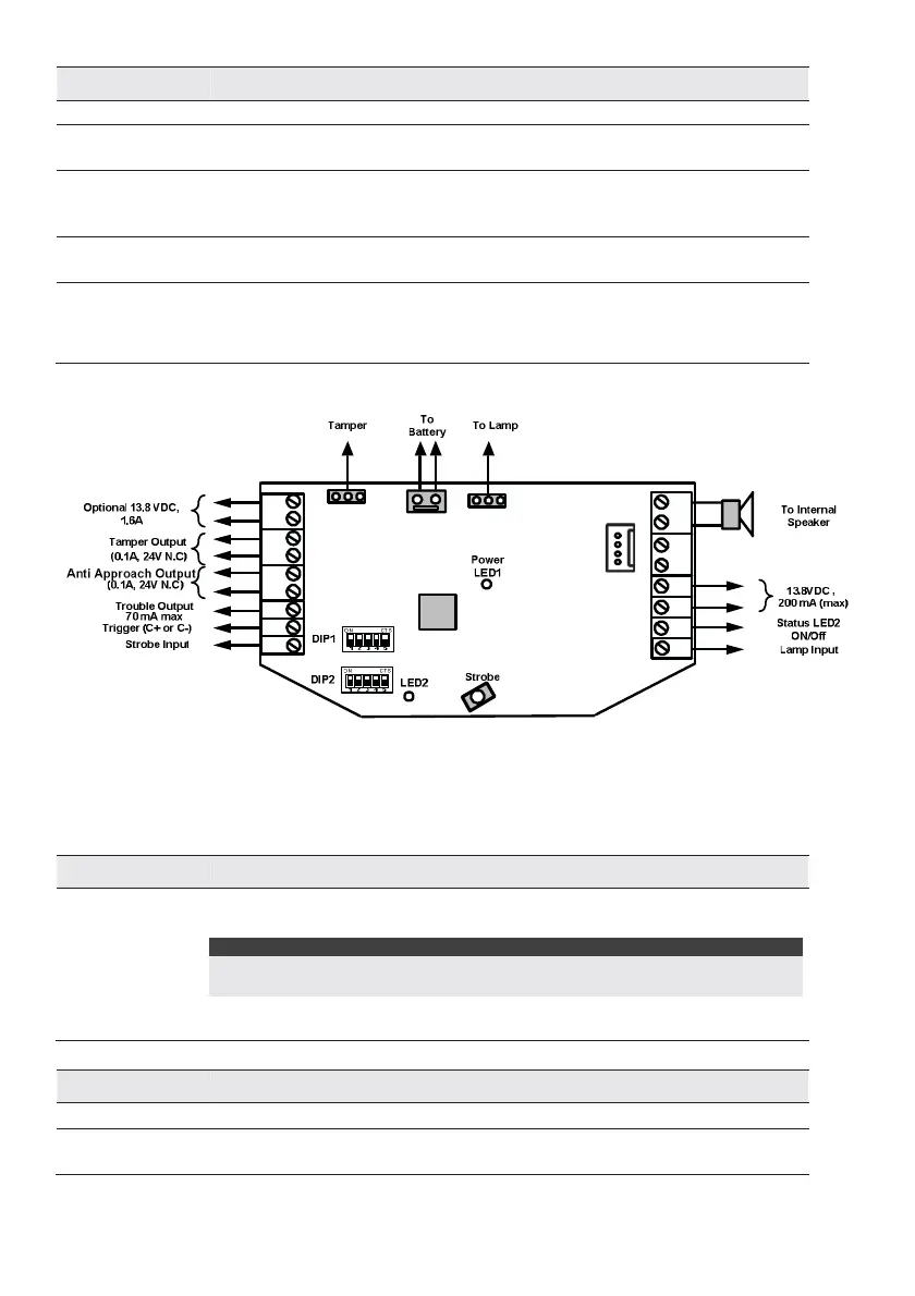
Speaker Used for the connection of the internal speaker (8Ω 30W).
BUS
GRN / YEL
Not used in Stand-Alone configuration.
AUX RED/ COM
BLACK
Input DC power terminals.
The maximum current drain from these terminals is 200mA. In BUS configuration,
connect the wires according to the indicated colors.
LED
(Status LED2)
This terminal is for triggering LED2:- LED2 activates when LED Terminal is connected
to COM (0V).
LAMP Input Connect LAMP Terminal to COM (0v) to turn Cover Illumination ON (if fitted).
In BUS mode, lamp input works as defined in the control panel. Note: Connection of
LAMP Terminal to COM over-rides BUS Control, LAMP will be ON if LAMP Terminal is
connected to COM.
PROXRTN FEED+ PS - TRBL
C
- +
TAMPER
STB
BUS
GRNYEL
COM
BLK
SPEAKERLAMP LED
AUX
RED
BUS
Figure 1: Stand Alone Wiring
BUS Mode
The following explains the various wiring and connection procedures that must be performed when wiring
the sounder:
Left Terminal Description
PS +
PS-
Use these terminals to connect an alternative power supply 13.8VDC 1.6A to the
sounder.
NOTES:
The maximum current that the sounder can draw from these terminals is 1.6A
compared to 200 mA from the AUX RED and COM BLK terminals.
When a power supply is connected to these terminals there is no need to connect a
power supply to the AUX RED and COM BLK terminals.
Right Terminal Description
Speaker
Used for the connection of the internal speaker (8Ω 30W).
BUS YEL/ BUS
GRN
Connect these terminals in BUS mode configuration, point to point according to the
indicated colors