14
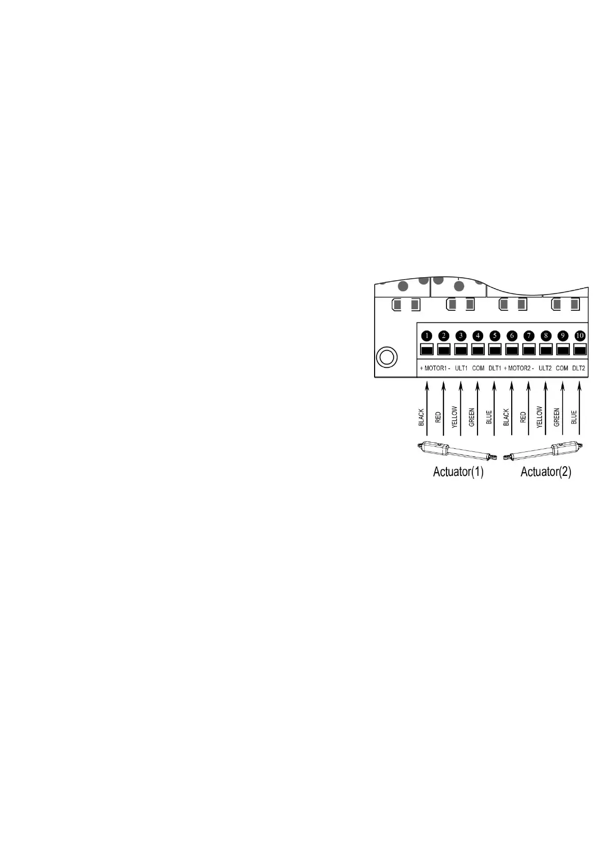
Motor connection for PULL-TO-OPEN
Actuator 1
Insert the stripped cable wires into the appropriate terminals on the opener terminals block. The red wire should
be inserted into the “MOTOR1+” terminal, the black wire into “MOTOR1-“, the blue wire into ULT1, the green
wire into COM, and the yellow wire into DLT1 terminal.
Actuator 2
Similar as the connection of Actuator 1, insert the stripped cable wires into the appropriate terminals on the opener
terminals block. The red wire should be inserted into the MOTOR2+ terminal, the black wire into MOTOR2-, the
blue wire into ULT2, the green wire into COM, and the yellow wire into DLT2 terminal.
NOTE: It is recommended that Gate Opener 1 is installed in the Master Gate, and Gate Opener 2 is installed in
the Slave Gate.
Motor connection for PUSH-TO-OPEN
The motors’ power wires and limit wires connection by “Push to
Open” is different from the connection by “Pull to Open”. So motor 1
and motor 2 wires should be connected to the control box as the
instruction on the right. The black wire should be inserted into the
Motor+ terminal, the red wire should be inserted into the Motor-
terminal, the yellow wire into ULT1 terminal, the blue wire into DLT1
terminal and the green wire is still into COM terminal.
Alarm Lamp (optional)
The red wire of the alarm lamp should be inserted into either LAMP
(#11) terminal, the white wire into the other one (#12).
Back-up Battery (optional)
The “24V+” of the battery should be wired to the BAT+ (#13) terminal, “24V-” should be wired to “BAT-” (#14)
terminal.
Recommend strongly to use the controller LM118 (WA4004
)
to connect Battery with battery’s Terminal of
control board if the battery is used as the primary power supply in system (such as SOL PLUS KIT). Please
refer to the user manual of control LM118
(
WA4004
)
separated.
Photocell Beam System (PBS) (optional)
Use a 2-core cable to connect the “- ~” terminal of the photocell’s emitter to the “14” terminal, the “+ ~” terminal
to the “9” terminal. Also the “- ~” and “+ ~” terminals of the photocell’s receiver should be connected to the “14”
and “9” terminals in parallel.
Use another 2-core cable to connect the “COM” terminal of the receiver to the “17” terminal, the “NC” terminal to
the “18” terminal.
Push Button (optional)
The push button should be wired to the “19” and “20” terminals. The gate operator works alternately by pushing
the button (open-stop-close-stop-open).
Loop Detector (optional)