
M
Misty KellerSep 18, 2025
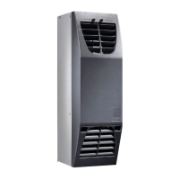
How to fix ALA10 alarm on Rittal LCP Rack DX 12?
- AAmanda SmithSep 18, 2025
If your Rittal Air Conditioner displays an ALA10 alarm indicating that Probe B10 is faulty or disconnected, it could be due to sensor failure or the sensor not being correctly connected. Check the connection on the motherboard or replace the sensor.