BLOCKSYSTEM FS Pag. 27 Rev. 02 02/07
UK
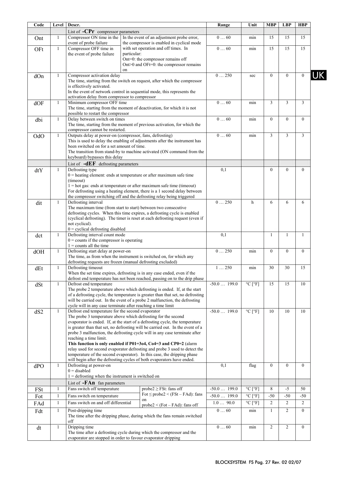
Code Level Descr. Range Unit MBP LBP HBP
List of -CPr compressor parameters
Ont
1 Compressor ON time in the
event of probe failure
0 … 60 min 15 15 15
OFt
1 Compressor OFF time in
the event of probe failure
In the event of an adjustment probe error,
the compressor is enabled in cyclical mode
with set operation and off times. In
particular:
Ont=0: the compressor remains off
Ont>0 and OFt=0: the compressor remains
on
0 … 60 min 15 15 15
dOn
1 Compressor activation delay
The time, starting from the switch on request, after which the compressor
is effectively activated.
In the event of network control in sequential mode, this represents the
activation delay from compressor to compressor
0 … 250 sec 0 0 0
dOF
1 Minimum compressor OFF time
The time, starting from the moment of deactivation, for which it is not
possible to restart the compressor
0 … 60 min 3 3 3
dbi
1 Delay between switch on times
The time, starting from the moment of previous activation, for which the
compressor cannot be restarted.
0 … 60 min 0 0 0
OdO
1 Outputs delay at power-on (compressor, fans, defrosting)
This is used to delay the enabling of adjustments after the instrument has
been switched on for a set amount of time.
The transition from stand-by to machine activated (ON command from the
keyboard) bypasses this delay
0 … 60 min 3 3 3
List of -dEF defrosting parameters
dtY
1 Defrosting type
0 = heating element: ends at temperature or after maximum safe time
(timeout)
1 = hot gas: ends at temperature or after maximum safe time (timeout)
For defrosting using a heating element, there is a 1 second delay between
the compressor switching off and the defrosting relay being triggered
0,1 0 0 0
dit
1 Defrosting interval
The maximum time (from start to start) between two consecutive
defrosting cycles. When this time expires, a defrosting cycle is enabled
(cyclical defrosting). The timer is reset at each defrosting request (even if
not cyclical).
0 = cyclical defrosting disabled
0 … 250 h 6 6 6
dct
1 Defrosting interval count mode
0 = counts if the compressor is operating
1 = counts all the time
0,1 1 1 1
dOH
1 Defrosting start delay at power-on
The time, as from when the instrument is switched on, for which any
defrosting requests are frozen (manual defrosting excluded)
0 … 250 min 0 0 0
dEt
1 Defrosting timeout
When the set time expires, defrosting is in any case ended, even if the
defrost end temperature has not been reached, passing on to the drip phase
1 … 250 min 30 30 15
dSt
1 Defrost end temperature
The probe 2 temperature above which defrosting is ended. If, at the start
of a defrosting cycle, the temperature is greater than that set, no defrosting
will be carried out. In the event of a probe 2 malfunction, the defrosting
cycle will in any case terminate after reaching a time limit
-50.0 … 199.0 °C [°F] 15 15 10
dS2
1 Defrost end temperature for the second evaporator
The probe 3 temperature above which defrosting for the second
evaporator is ended. If, at the start of a defrosting cycle, the temperature
is greater than that set, no defrosting will be carried out. In the event of a
probe 3 malfunction, the defrosting cycle will in any case terminate after
reaching a time limit.
This function is only enabled if P01=3o4, Co4=3 and CP0=2 (alarm
relay used for second evaporator defrosting and probe 3 used to detect the
temperature of the second evaporator). In this case, the dripping phase
will begin after the defrosting cycles of both evaporators have ended.
-50.0 … 199.0 °C [°F] 10 10 10
dPO
1 Defrosting at power-on
0 = disabled
1 = defrosting when the instrument is switched on
0,1 flag 0 0 0
List of -FAn fan parameters
FSt
1 Fans switch off temperature -50.0 … 199.0 °C [°F] 8 -5 50
Fot
1 Fans switch on temperature -50.0 … 199.0 °C [°F] -50 -50 -50
FAd
1 Fans switch on and off differential
probe2 ≥ FSt: fans off
Fot ≤ probe2 < (FSt – FAd): fans
on
probe2 < (Fot – FAd): fans off
1.0 … 90.0 °C [°F] 2 2 2
Fdt
1 Post-dripping time
The time after the dripping phase, during which the fans remain switched
off
0 … 60 min 1 2 0
dt
1 Dripping time
The time after a defrosting cycle during which the compressor and the
evaporator are stopped in order to favour evaporator dripping
0 … 60 min 2 2 0
 Loading...