BLOCKSYSTEM FS Pag. 28 Rev. 02 02/07
UK
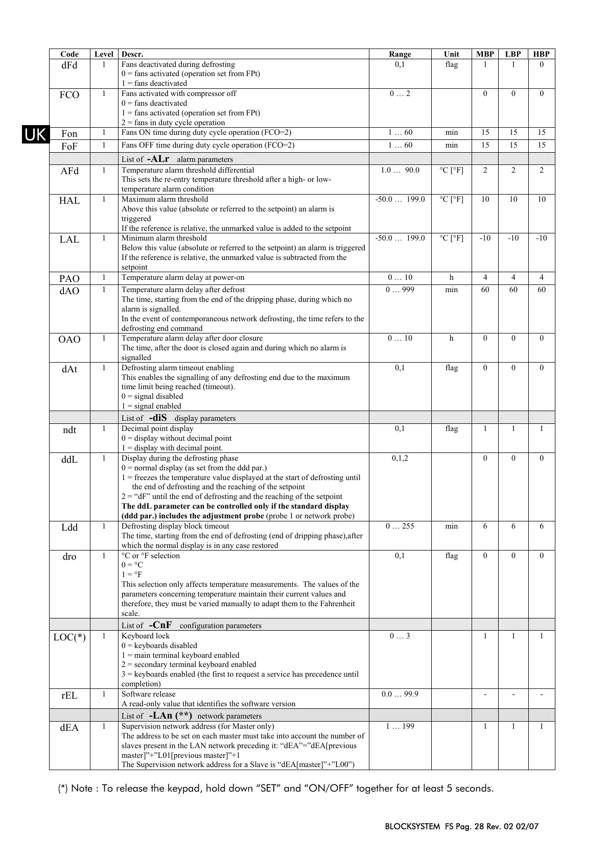
Code Level Descr. Range Unit MBP LBP HBP
dFd
1 Fans deactivated during defrosting
0 = fans activated (operation set from FPt)
1 = fans deactivated
0,1 flag 1 1 0
FCO
1 Fans activated with compressor off
0 = fans deactivated
1 = fans activated (operation set from FPt)
2 = fans in duty cycle operation
0 … 2 0 0 0
Fon
1 Fans ON time during duty cycle operation (FCO=2) 1 … 60 min 15 15 15
FoF
1 Fans OFF time during duty cycle operation (FCO=2) 1 … 60 min 15 15 15
List of -ALr alarm parameters
AFd
1 Temperature alarm threshold differential
This sets the re-entry temperature threshold after a high- or low-
temperature alarm condition
1.0 … 90.0 °C [°F] 2 2 2
HAL
1 Maximum alarm threshold
Above this value (absolute or referred to the setpoint) an alarm is
triggered
If the reference is relative, the unmarked value is added to the setpoint
-50.0 … 199.0 °C [°F] 10 10 10
LAL
1 Minimum alarm threshold
Below this value (absolute or referred to the setpoint) an alarm is triggered
If the reference is relative, the unmarked value is subtracted from the
setpoint
-50.0 … 199.0 °C [°F] -10 -10 -10
PAO
1 Temperature alarm delay at power-on 0 … 10 h 4 4 4
dAO
1 Temperature alarm delay after defrost
The time, starting from the end of the dripping phase, during which no
alarm is signalled.
In the event of contemporaneous network defrosting, the time refers to the
defrosting end command
0 … 999 min 60 60 60
OAO
1 Temperature alarm delay after door closure
The time, after the door is closed again and during which no alarm is
signalled
0 … 10 h 0 0 0
dAt
1 Defrosting alarm timeout enabling
This enables the signalling of any defrosting end due to the maximum
time limit being reached (timeout).
0 = signal disabled
1 = signal enabled
0,1 flag 0 0 0
List of -diS display parameters
ndt
1 Decimal point display
0 = display without decimal point
1 = display with decimal point.
0,1 flag 1 1 1
ddL
1 Display during the defrosting phase
0 = normal display (as set from the ddd par.)
1 = freezes the temperature value displayed at the start of defrosting until
the end of defrosting and the reaching of the setpoint
2 = “dF” until the end of defrosting and the reaching of the setpoint
The ddL parameter can be controlled only if the standard display
(ddd par.) includes the adjustment probe (probe 1 or network probe)
0,1,2 0 0 0
Ldd
1 Defrosting display block timeout
The time, starting from the end of defrosting (end of dripping phase),after
which the normal display is in any case restored
0 … 255 min 6 6 6
dro
1 °C or °F selection
0 = °C
1 = °F
This selection only affects temperature measurements. The values of the
parameters concerning temperature maintain their current values and
therefore, they must be varied manually to adapt them to the Fahrenheit
scale.
0,1 flag 0 0 0
List of -CnF configuration parameters
LOC(*)
1 Keyboard lock
0 = keyboards disabled
1 = main terminal keyboard enabled
2 = secondary terminal keyboard enabled
3 = keyboards enabled (the first to request a service has precedence until
completion)
0 … 3 1 1 1
rEL
1 Software release
A read-only value that identifies the software version
0.0 … 99.9 - - -
List of -LAn (**) network parameters
dEA
1 Supervision network address (for Master only)
The address to be set on each master must take into account the number of
slaves present in the LAN network preceding it: “dEA”=”dEA[previous
master]”+”L01[previous master]”+1
The Supervision network address for a Slave is “dEA[master]”+”L00”)
1 … 199 1 1 1
(*) Note : To release the keypad, hold down “SET” and “ON/OFF” together for at least 5 seconds.
 Loading...