the woodbox in correspondence of the combustion chamber. For the connection, we suggest to
use a flexible pipe.
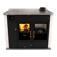
Picture 9 - Installation with air intake in the room of installation and installation with air intake directly connected to the wood fired
cooker/thermal cooker.
A B C
Picture 10 - Possible connections of the air intake of the cooker/thermal cooker.
A= External air intake not connected, B= External air intake on the floor, C=External air intake on the wall.
To make the connection easier we suggest to make the external air intake on the floor in
correspondence with the internal part of the plinth, or on the wall through the rear part of the
device (see table 2 and picture 11). Are also possible other solutions for the connection but they
must be decided together with Rizzoli.
WARNING! Aspiring hoods or extracting air fans in the room may generate
problems to the device if there is not a suited air intake or in case of air intake sub-
dimensioned.
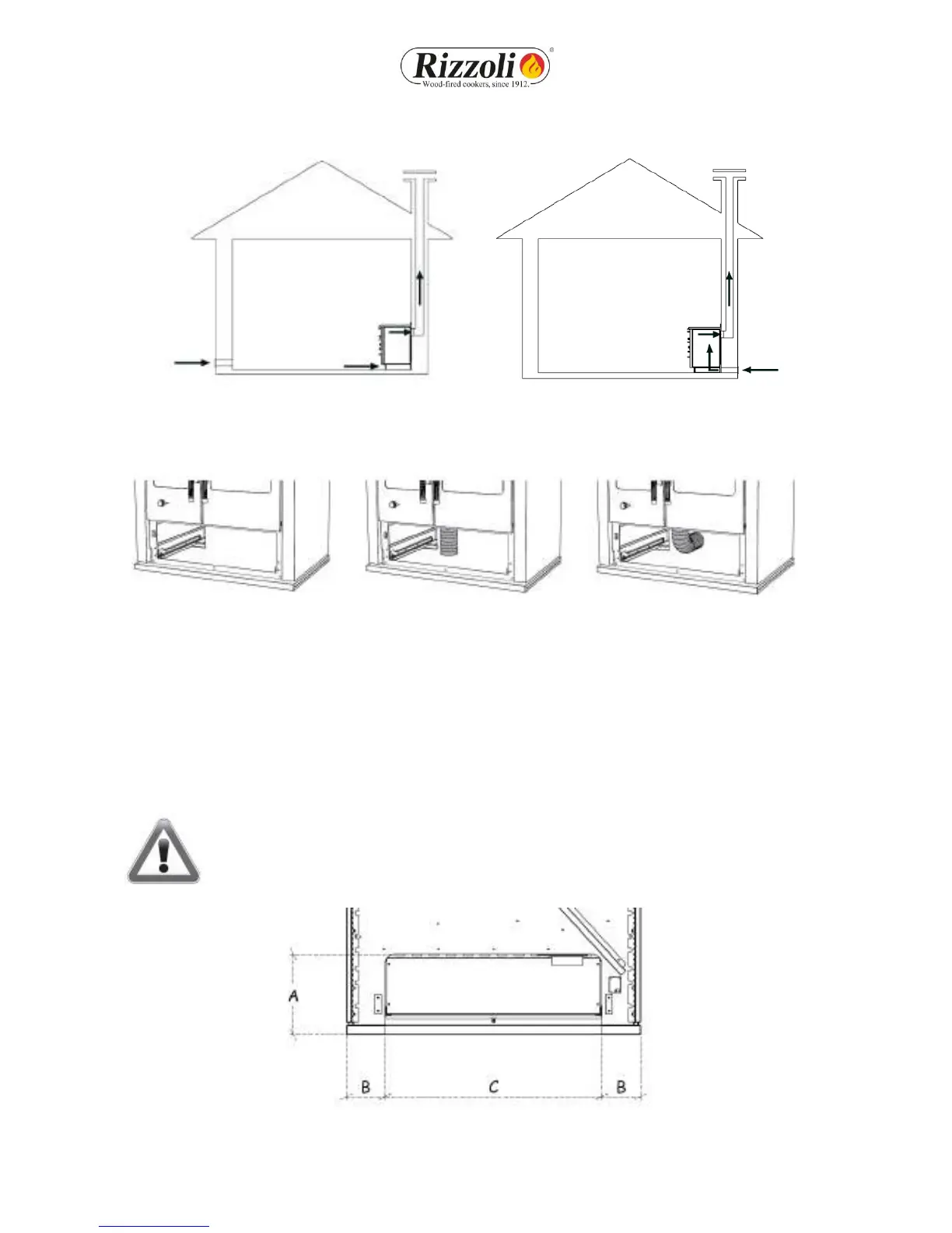
Picture 11 - Rear sight of the plinth of the wood fired cooker or thermal cooker and specifies for the connection with the air intake.
 Loading...