2. CONNECTING
IMSRM04-E8
15
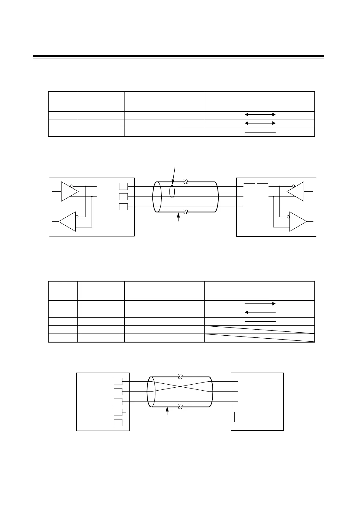
RS-485
Pin number and signal name
Pin No. Mark Name
Signal Direction
Operation panel Host computer
2 T/R(A) Send data/Receive data
14 T/R(B) Send data/Receive data
8 SG Ground for signal
Contents of communication cable wiring
RS-232C
Pin number and signal name
Pin No. Mark Name
Signal Direction
Operation panel Host computer
2 SD (TXD) Send data
3 RD (RXD) Receive data
7 SG (GND) Ground for signal
4 RS (RTS) Request to send
5 CS (CTS) Clear to send
Contents of communication cable wiring
2
3
7
Host computer
Shield wire
(Maximum connections: 1 unit)
SD (TXD)
RD (RXD)
SG (GND)
RS (RTS)
CS (CTS)
SD (TXD)
RD (RXD)
SG (GND)
RS (RTS)
CS (CTS)
4
5
*
*
*Short RS and CS within connector
2
14
8
Shielded twisted
pair wire
(Maximum connections: 16 units)
TXD and RXD : negative logic.
TXR/RXD
TXR/RXD
SG
T/R (A)
T/R (B)
SG
Paired wire
Host computer
Operation panel
Operation panel
RS-232C
 Loading...