5. COMMUNICATION IDENTIFIERS
IMSRM04-E8
41
5.2 Identifiers Function Explanation
Identifier M1: Measured value (PV) input
Read only identifier which defines the input measured value from the control unit.
Data range: Within input range
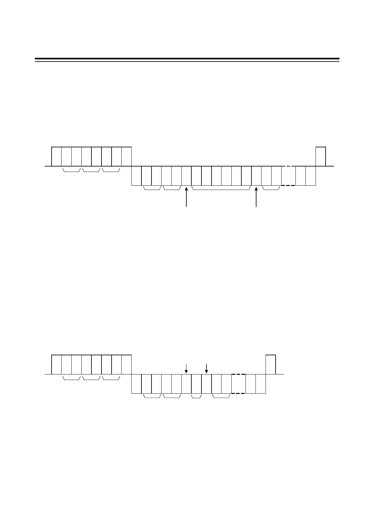
Polling example:
E
O
T
E
N
Q
A
C
K
S
T
X
01 400. 0, 02
...
E
T
X
B
C
C
* Omit the operation panel address when the connection is made directly to control unit.
Identifier AA: First alarm condition
Identifier AB: Second alarm condition
Read only identifier which defines each channel alarm condition of the control unit.
Data range: 0: OFF
1: ON
Polling example:
E
O
T
E
N
Q
A
C
K
S
T
X
01 0, 02
...
E
T
X
B
C
C
* Omit the operation panel address when the connection is made directly to control unit.
Identifier
Comma
Space
Data
(1 digit)
Next to identifier
Channel
No.
Channel
No.
Identifier
Comma
Space
Next to identifier
Data (6 digits)
Identifier
Channel
No.
Channel
No.
Operation
panel
address
*
Identifier
Unit
address
Operation
panel
address
*
Unit
address
Host computer sendHost computer send
SR Mini SYSTEM send
Host computer send Host computer send
SR Mini SYSTEM send
 Loading...